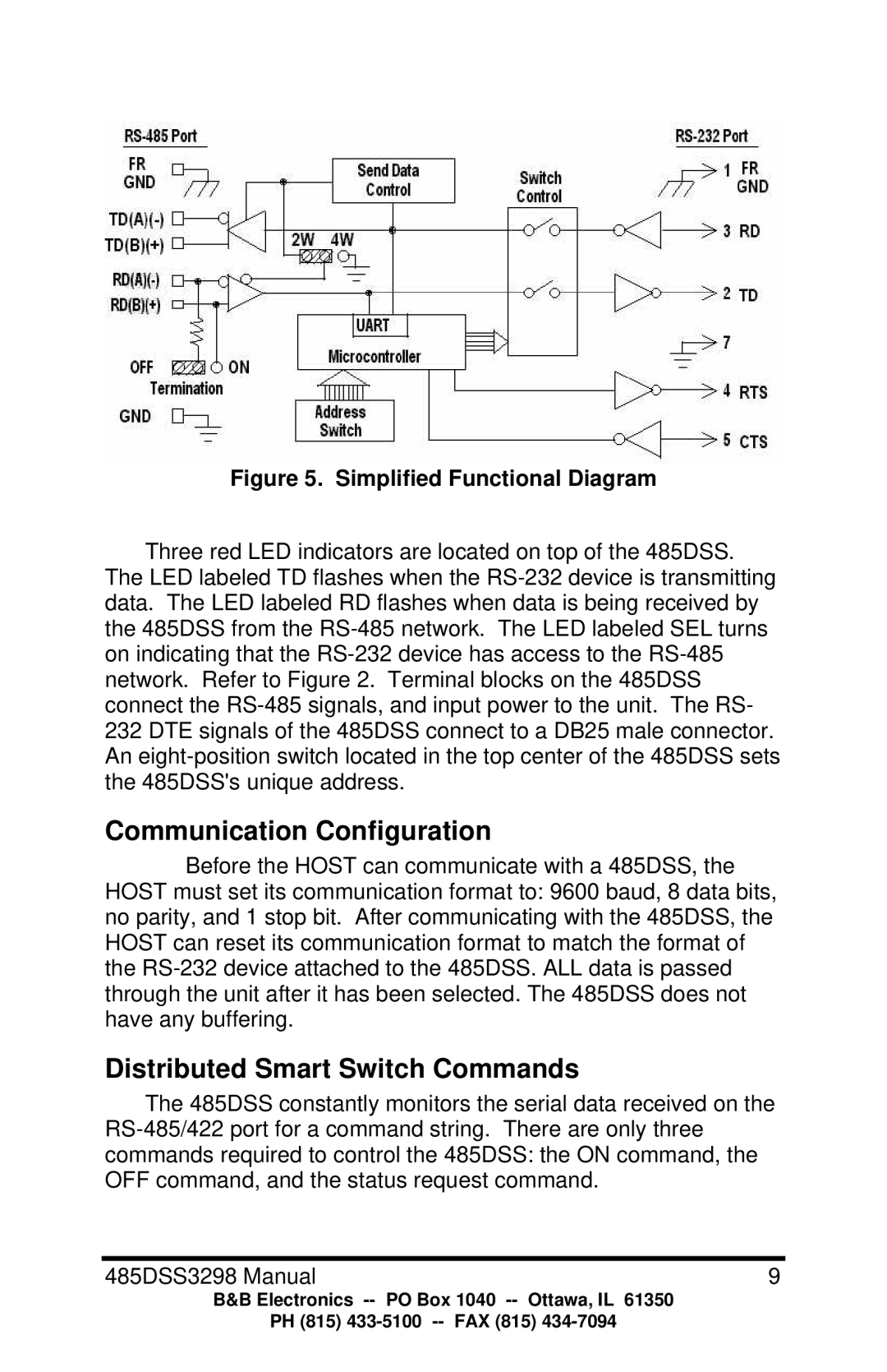
Figure 5. Simplified Functional Diagram
Three red LED indicators are located on top of the 485DSS.
The LED labeled TD flashes when the RS-232 device is transmitting data. The LED labeled RD flashes when data is being received by the 485DSS from the RS-485 network. The LED labeled SEL turns on indicating that the RS-232 device has access to the RS-485 network. Refer to Figure 2. Terminal blocks on the 485DSS connect the RS-485 signals, and input power to the unit. The RS- 232 DTE signals of the 485DSS connect to a DB25 male connector. An eight-position switch located in the top center of the 485DSS sets the 485DSS's unique address.
Communication Configuration
Before the HOST can communicate with a 485DSS, the HOST must set its communication format to: 9600 baud, 8 data bits, no parity, and 1 stop bit. After communicating with the 485DSS, the HOST can reset its communication format to match the format of the RS-232 device attached to the 485DSS. ALL data is passed through the unit after it has been selected. The 485DSS does not have any buffering.
Distributed Smart Switch Commands
The 485DSS constantly monitors the serial data received on the RS-485/422 port for a command string. There are only three commands required to control the 485DSS: the ON command, the OFF command, and the status request command.
B&B Electronics -- PO Box 1040 -- Ottawa, IL 61350
PH (815) 433-5100 -- FAX (815) 434-7094