PARTS
Parent Tray
|
| Child Tray | Front Wheels |
|
|
| |
| Canopy |
|
|
| Snap N Go Attachment | Foot Rest | Rear Wheels |
Stroller | See Page 8 |
|
|
|
|
|
ASSEMBLING
TO ENSURE SAFE OPERATION OF YOUR STROLLER, PLEASE FOLLOW THESE INSTRUCTIONS CAREFULLY. RETAIN THESE INSTRUCTIONS FOR FUTURE REFERENCE
ASSEMBLY
1.Remove stroller from box. The front wheels, rear wheels, child tray, and canopy need to be installed prior to use.
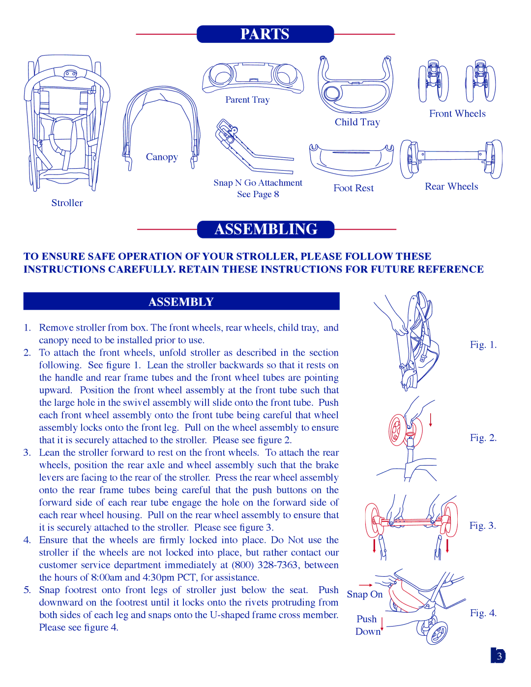
2.To attach the front wheels, unfold stroller as described in the section following. See figure 1. Lean the stroller backwards so that it rests on the handle and rear frame tubes and the front wheel tubes are pointing upward. Position the front wheel assembly at the front tube such that the large hole in the swivel assembly will slide onto the front tube. Push each front wheel assembly onto the front tube being careful that wheel assembly locks onto the front leg. Pull on the wheel assembly to ensure that it is securely attached to the stroller. Please see figure 2.
3.Lean the stroller forward to rest on the front wheels. To attach the rear wheels, position the rear axle and wheel assembly such that the brake levers are facing to the rear of the stroller. Press the rear wheel assembly onto the rear frame tubes being careful that the push buttons on the forward side of each rear tube engage the hole on the forward side of each rear wheel housing. Pull on the rear wheel assembly to ensure that it is securely attached to the stroller. Please see figure 3.
4.Ensure that the wheels are firmly locked into place. Do Not use the stroller if the wheels are not locked into place, but rather contact our customer service department immediately at (800)
5.Snap footrest onto front legs of stroller just below the seat. Push downward on the footrest until it locks onto the rivets protruding from both sides of each leg and snaps onto the
Snap On
Push
Down![]()
Fig. 1.
Fig. 2.
Fig. 3.
Fig. 4.
3
