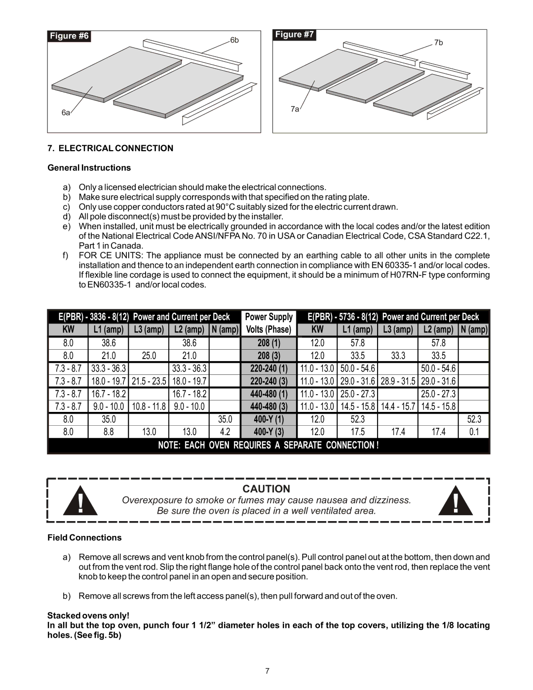
Figure #6 |
6b |
6a |
7. ELECTRICAL CONNECTION
Figure #7 |
7b |
7a |
General Instructions
a)Only a licensed electrician should make the electrical connections.
b)Make sure electrical supply corresponds with that specified on the rating plate.
c)Only use copper conductors rated at 90°C suitably sized for the electric current drawn.
d)All pole disconnect(s) must be provided by the installer.
e)When installed, unit must be electrically grounded in accordance with the local codes and/or the latest edition of the National Electrical Code ANSI/NFPA No. 70 in USA or Canadian Electrical Code, CSA Standard C22.1, Part 1 in Canada.
f)FOR CE UNITS: The appliance must be connected by an earthing cable to all other units in the complete installation and thence to an independent earth connection in compliance with EN
E(PBR) - 3836 - 8(12) Power and Current per Deck |
|
| Power Supply |
|
|
| E(PBR) - 5736 - 8(12) Power and Current per Deck | ||||||||||||||
KW |
| L1 (amp) | L3 (amp) |
| L2 (amp) | N (amp) |
|
| Volts (Phase) |
|
|
| KW |
| L1 (amp) | L3 (amp) |
| L2 (amp) | N (amp) | ||
8.0 | 38.6 |
| 38.6 |
|
| 208 (1) |
|
| 12.0 | 57.8 |
| 57.8 |
| ||||||||
8.0 |
| 21.0 | 25.0 |
| 21.0 |
|
|
| 208 (3) |
|
| 12.0 |
| 33.5 | 33.3 |
| 33.5 |
| |||
7.3 - 8.7 |
| 33.3 - 36.3 |
|
| 33.3 - 36.3 |
|
|
|
|
|
|
| 11.0 - 13.0 |
| 50.0 - 54.6 |
|
| 50.0 - 54.6 |
| ||
7.3 - 8.7 |
| 18.0 - 19.7 | 21.5 - 23.5 |
| 18.0 - 19.7 |
|
|
|
|
| 11.0 - 13.0 |
| 29.0 - 31.6 | 28.9 - 31.5 |
| 29.0 - 31.6 |
| ||||
7.3 - 8.7 |
| 16.7 - 18.2 |
|
| 16.7 - 18.2 |
|
|
|
|
|
|
| 11.0 - 13.0 |
| 25.0 - 27.3 |
|
| 25.0 - 27.3 |
| ||
7.3 - 8.7 |
| 9.0 - 10.0 | 10.8 - 11.8 |
| 9.0 - 10.0 |
|
|
|
|
| 11.0 - 13.0 |
| 14.5 - 15.8 | 14.4 - 15.7 |
| 14.5 - 15.8 |
| ||||
8.0 |
| 35.0 |
|
|
| 35.0 |
|
|
|
|
|
| 12.0 |
| 52.3 |
|
|
| 52.3 | ||
8.0 |
| 8.8 | 13.0 |
| 13.0 | 4.2 |
|
|
|
| 12.0 |
| 17.5 | 17.4 |
| 17.4 | 0.1 | ||||
NOTE: EACH OVEN REQUIRES A SEPARATE CONNECTION !
CAUTION
! | Overexposure to smoke or fumes may cause nausea and dizziness. | ! |
Be sure the oven is placed in a well ventilated area. |
Field Connections
a)Remove all screws and vent knob from the control panel(s). Pull control panel out at the bottom, then down and out from the vent rod. Slip the right flange hole of the control panel back onto the vent rod, then replace the vent knob to keep the control panel in an open and secure position.
b)Remove all screws from the left access panel(s), then pull forward and out of the oven.
Stacked ovens only!
In all but the top oven, punch four 1 1/2” diameter holes in each of the top covers, utilizing the 1/8 locating holes. (See fig. 5b)
7
