Section 4
Operation
Operator Control Panel
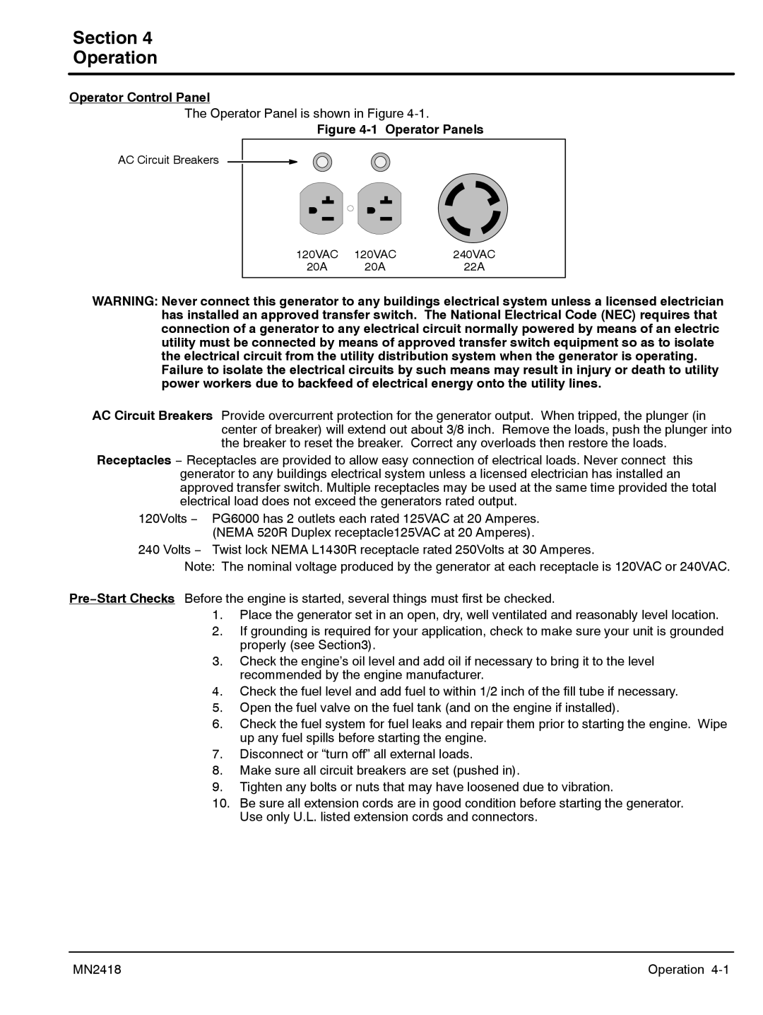
The Operator Panel is shown in Figure
Figure 4-1 Operator Panels
AC Circuit Breakers
120VAC | 120VAC | 240VAC |
20A | 20A | 22A |
WARNING: Never connect this generator to any buildings electrical system unless a licensed electrician has installed an approved transfer switch. The National Electrical Code (NEC) requires that connection of a generator to any electrical circuit normally powered by means of an electric utility must be connected by means of approved transfer switch equipment so as to isolate the electrical circuit from the utility distribution system when the generator is operating. Failure to isolate the electrical circuits by such means may result in injury or death to utility power workers due to backfeed of electrical energy onto the utility lines.
AC Circuit Breakers Provide overcurrent protection for the generator output. When tripped, the plunger (in center of breaker) will extend out about 3/8 inch. Remove the loads, push the plunger into the breaker to reset the breaker. Correct any overloads then restore the loads.
Receptacles − Receptacles are provided to allow easy connection of electrical loads. Never connect this generator to any buildings electrical system unless a licensed electrician has installed an approved transfer switch. Multiple receptacles may be used at the same time provided the total electrical load does not exceed the generators rated output.
120Volts − PG6000 has 2 outlets each rated 125VAC at 20 Amperes. (NEMA 520R Duplex receptacle125VAC at 20 Amperes).
240 Volts − Twist lock NEMA L1430R receptacle rated 250Volts at 30 Amperes.
Note: The nominal voltage produced by the generator at each receptacle is 120VAC or 240VAC.
Pre−Start Checks Before the engine is started, several things must first be checked.
1.Place the generator set in an open, dry, well ventilated and reasonably level location.
2.If grounding is required for your application, check to make sure your unit is grounded properly (see Section3).
3.Check the engine’s oil level and add oil if necessary to bring it to the level recommended by the engine manufacturer.
4.Check the fuel level and add fuel to within 1/2 inch of the fill tube if necessary.
5.Open the fuel valve on the fuel tank (and on the engine if installed).
6.Check the fuel system for fuel leaks and repair them prior to starting the engine. Wipe up any fuel spills before starting the engine.
7.Disconnect or “turn off” all external loads.
8.Make sure all circuit breakers are set (pushed in).
9.Tighten any bolts or nuts that may have loosened due to vibration.
10.Be sure all extension cords are in good condition before starting the generator. Use only U.L. listed extension cords and connectors.
MN2418 | Operation |