Manuals
/
Baldor
/
Lawn and Garden
/
Portable Generator
Baldor
PG 6000
manual
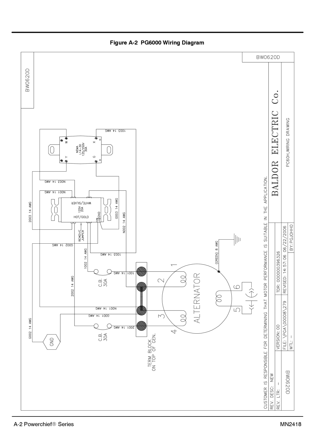
Figure A-2 PG6000 Wiring Diagram
Models:
PG 6000
1
22
26
26
Download
26 pages
39.14 Kb
19
20
21
22
23
24
25
26
Page 22
Image 22
Figure
A-2
PG6000 Wiring Diagram
A-2
PowerchiefR Series
MN2418
Page 21
Page 23
Page 22
Image 22
Page 21
Page 23
Contents
PG 6000 Generator
California Proposition 65 Warning
Table of Contents
Ii Table of Contents MN2418
Section Product Safety Information
Read This Manual Thoroughly
Property
Precaution Statements Used In This Manual
Operation
Operation Warning Statements
Burn Installation
Maintenance
Product Safety Information MN2418
Section General Information
Limited Warranty
Labor Parts
General Information MN2418
Section Receiving & Installation
PG6000 Generator Storage
Physical Location
Single Phase Power Receptacle Description
Receptacle Connections
Engine Oil
Frame Ground Connection
Use of Electric Motor Loads
Section Operation
Operator Control Panel
Start−Up Procedure Recoil Start
Stopping Procedure
General
Section Troubleshooting and Maintenance
Engine
Troubleshooting Guide
Problems and Solutions
Service
Appendix a PG6000 Connections
Figure A-2 PG6000 Wiring Diagram
Appendix B Special Information for California
Special Information for California MN2418
Baldor District Offices
Baldor Electric Company
Top
Page
Image
Contents