28 | B E O V I S I O N M X 4 0 0 2 … |
|
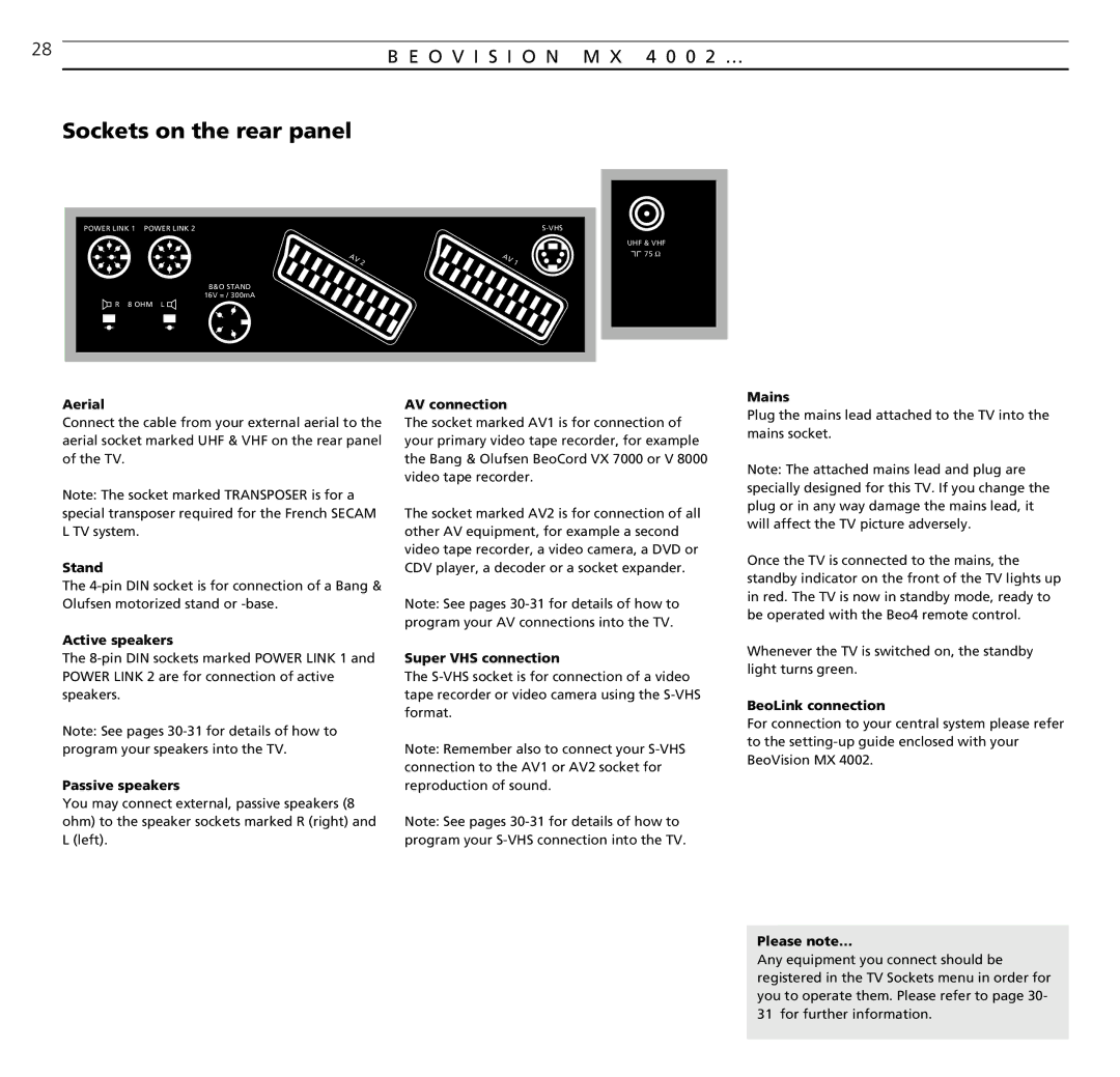
Sockets on the rear panel
POWER LINK 1 POWER LINK 2S-VHS
A | V | 2 | A | V | 1 |
|
|
|
|
B&O STAND
16V = / 300mA
R 8 OHM L
UHF & VHF ![]()
![]() 75 Ω
75 Ω
Aerial
Connect the cable from your external aerial to the aerial socket marked UHF & VHF on the rear panel of the TV.
Note: The socket marked TRANSPOSER is for a special transposer required for the French SECAM L TV system.
Stand
The
Active speakers
The
Note: See pages
Passive speakers
You may connect external, passive speakers (8 ohm) to the speaker sockets marked R (right) and L (left).
AV connection
The socket marked AV1 is for connection of your primary video tape recorder, for example the Bang & Olufsen BeoCord VX 7000 or V 8000 video tape recorder.
The socket marked AV2 is for connection of all other AV equipment, for example a second video tape recorder, a video camera, a DVD or CDV player, a decoder or a socket expander.
Note: See pages
Super VHS connection
The
Note: Remember also to connect your
Note: See pages
Mains
Plug the mains lead attached to the TV into the mains socket.
Note: The attached mains lead and plug are specially designed for this TV. If you change the plug or in any way damage the mains lead, it will affect the TV picture adversely.
Once the TV is connected to the mains, the standby indicator on the front of the TV lights up in red. The TV is now in standby mode, ready to be operated with the Beo4 remote control.
Whenever the TV is switched on, the standby light turns green.
BeoLink connection
For connection to your central system please refer to the
Please note…
Any equipment you connect should be registered in the TV Sockets menu in order for you to operate them. Please refer to page 30- 31 for further information.