b) Connection of data signals
The display can be controlled remotely by a computer through the serial data bus. A typical example of this, is the MediCal software that controls the display. MediCal runs on a PC that is connected through the serial data bus. This PC is not necessarily the same computer as the one that produces the video signals.
Unlike the video signals, it is possible to
To connect the data signals:
1.Connect one end of the serial data cable to one of the PC’s COM ports. If the COM port has a
2.Connect the other end of the serial data cable to the Remote In connector {6} on the display’s rear panel.
3.For a
c)Connection of optical sensor
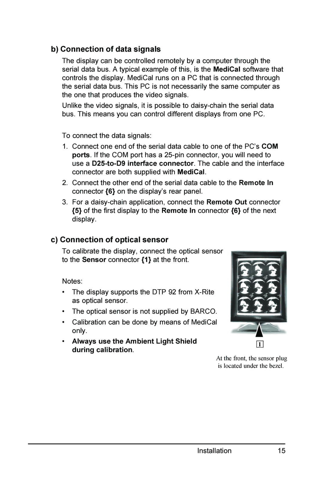
To calibrate the display, connect the optical sensor to the Sensor connector {1} at the front.
Notes:
•The display supports the DTP 92 from
•The optical sensor is not supplied by BARCO.
•Calibration can be done by means of MediCal only.
•Always use the Ambient Light Shield during calibration.
1
At the front, the sensor plug is located under the bezel.
Installation 15