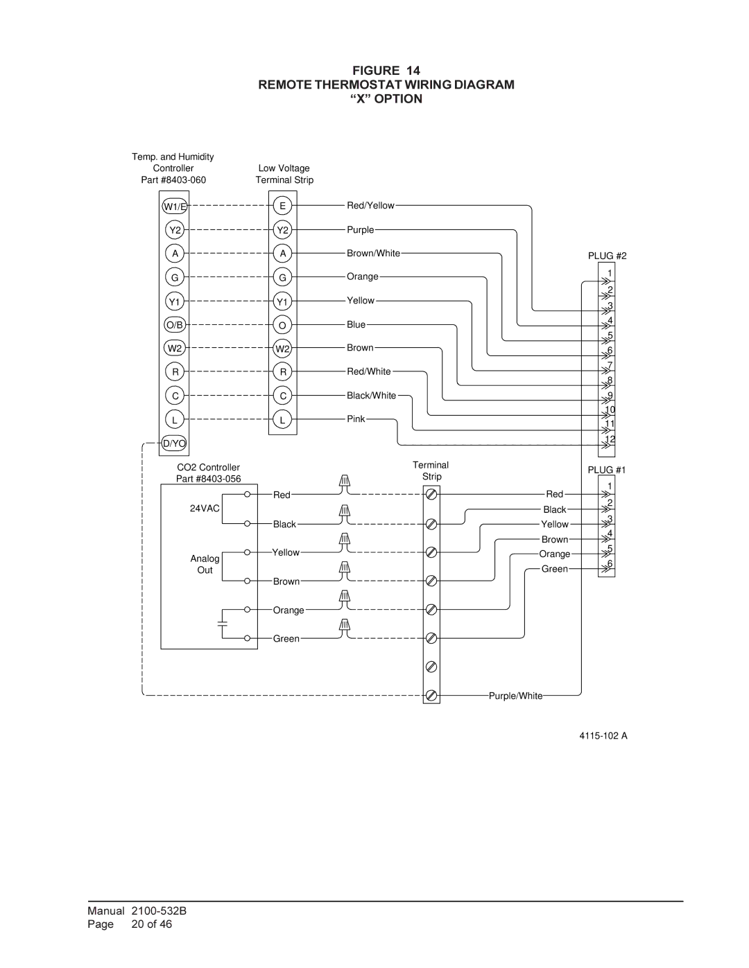
FIGURE 14
REMOTE THERMOSTAT WIRING DIAGRAM
“X” OPTION
Temp. and Humidity |
|
Controller | Low Voltage |
Part | Terminal Strip |
W1/E | E |
Y2 | Y2 |
A | A |
G | G |
Y1 | Y1 |
O/B | O |
W2 | W2 |
R | R |
C | C |
L | L |
D/YO |
|
CO2 Controller |
|
Part |
|
| Red |
24VAC |
|
| Black |
Analog | Yellow |
| |
Out |
|
| Brown |
| Orange |
| Green |
Red/Yellow
Purple
Brown/White
Orange
Yellow
Blue
Brown
Red/White
Black/White
Pink
Terminal
Strip
Red
Black
Yellow
Brown
Orange
Green
Purple/White
PLUG #2 1 2 3 4 5 6 7 8 9 10 11 12
PLUG #1 1 2 3 4 5 6
Manual | |
Page | 20 of 46 |
