QW SERIES GEOTHERMAL
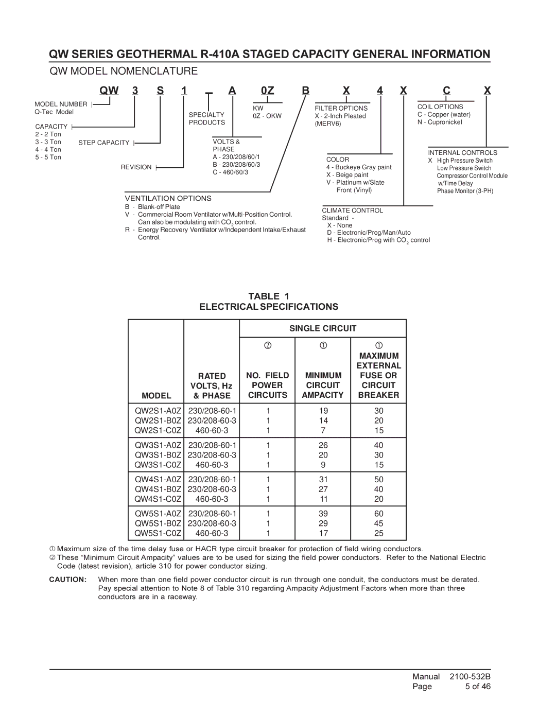
QW MODEL NOMENCLATURE
QW 3 S
1 |
| A | 0Z | B |
X 4 X C X
MODEL NUMBER ![]()
CAPACITY
2 - 2 Ton
3 - 3 Ton STEP CAPACITY
4 - 4 Ton
5 - 5 Ton
REVISION
|
|
|
|
|
|
|
| KW | |||
SPECIALTY | 0Z - OKW | ||||
PRODUCTS |
|
|
|
| |
|
|
|
|
|
|
VOLTS &
PHASE
A - 230/208/60/1
B - 230/208/60/3
C - 460/60/3
FILTER OPTIONS
X-
COLOR
4 - Buckeye Gray paint X - Beige paint
V - Platinum w/Slate Front (Vinyl)
COIL OPTIONS
C - Copper (water)
N - Cupronickel
INTERNAL CONTROLS
X• High Pressure Switch
•Low Pressure Switch
•Compressor Control Module w/Time Delay
•Phase Monitor
VENTILATION OPTIONS
B -
V - Commercial Room Ventilator
R- Energy Recovery Ventilator w/Independent Intake/Exhaust Control.
CLIMATE CONTROL
Standard -
X - None
D - Electronic/Prog/Man/Auto
H - Electronic/Prog with CO2 control
TABLE 1
ELECTRICAL SPECIFICATIONS
SINGLE CIRCUIT
|
| 2 | 1 | 1 |
|
|
|
| MAXIMUM |
|
|
|
| EXTERNAL |
| RATED | NO. FIELD | MINIMUM | FUSE OR |
| VOLTS, Hz | POWER | CIRCUIT | CIRCUIT |
MODEL | & PHASE | CIRCUITS | AMPACITY | BREAKER |
|
|
|
| |
1 | 19 | 30 | ||
1 | 14 | 20 | ||
1 | 7 | 15 | ||
|
|
|
| |
1 | 26 | 40 | ||
1 | 20 | 30 | ||
1 | 9 | 15 | ||
|
|
|
| |
1 | 31 | 50 | ||
1 | 27 | 40 | ||
1 | 11 | 20 | ||
|
|
|
| |
1 | 39 | 60 | ||
1 | 29 | 45 | ||
1 | 17 | 25 | ||
|
|
|
|
|
1 Maximum size of the time delay fuse or HACR type circuit breaker for protection of field wiring conductors.
2 These “Minimum Circuit Ampacity” values are to be used for sizing the field power conductors. Refer to the National Electric Code (latest revision), article 310 for power conductor sizing.
CAUTION: When more than one field power conductor circuit is run through one conduit, the conductors must be derated. Pay special attention to Note 8 of Table 310 regarding Ampacity Adjustment Factors when more than three conductors are in a raceway.
Manual | |
Page | 5 of 46 |
