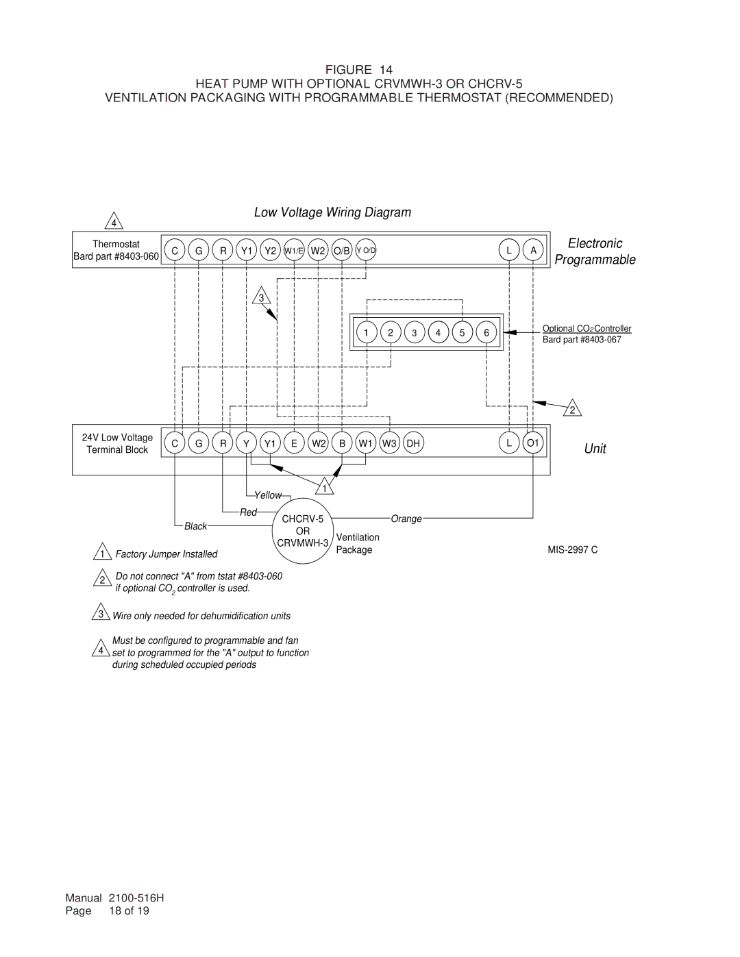
FIGURE 14
HEAT PUMP WITH OPTIONAL
VENTILATION PACKAGING WITH PROGRAMMABLE THERMOSTAT (RECOMMENDED)
4
Low Voltage Wiring Diagram
Thermostat | C | G | R | Y1 | Y2 | W1/E | W2 | O/B | Y O/D | L | A | Electronic | |
Bard part | Programmable | ||||||||||||
|
|
|
|
|
|
|
|
|
|
|
3
1 | 2 | 3 | 4 | 5 | 6 |
![]()
![]() Optional CO2 Controller
Optional CO2 Controller ![]() Bard part
Bard part
24V Low Voltage | C G R | Y Y1 E W2 | B W1 W3 DH | L O1 | |||
Terminal Block | |||||||
|
|
|
|
|
| ||
|
| Yellow | 1 |
|
| ||
|
|
|
|
| |||
| Black | Red |
| Orange |
| ||
|
|
|
| ||||
|
|
| OR | Ventilation |
| ||
|
|
|
|
| |||
|
|
|
| ||||
1 Factory Jumper Installed |
|
|
| Package |
| ||
|
|
|
|
| |||
2Do not connect "A" from tstat
3Wire only needed for dehumidification units Must be configured to programmable and fan
4set to programmed for the "A" output to function during scheduled occupied periods
2
Unit
Manual | |
Page | 18 of 19 |
