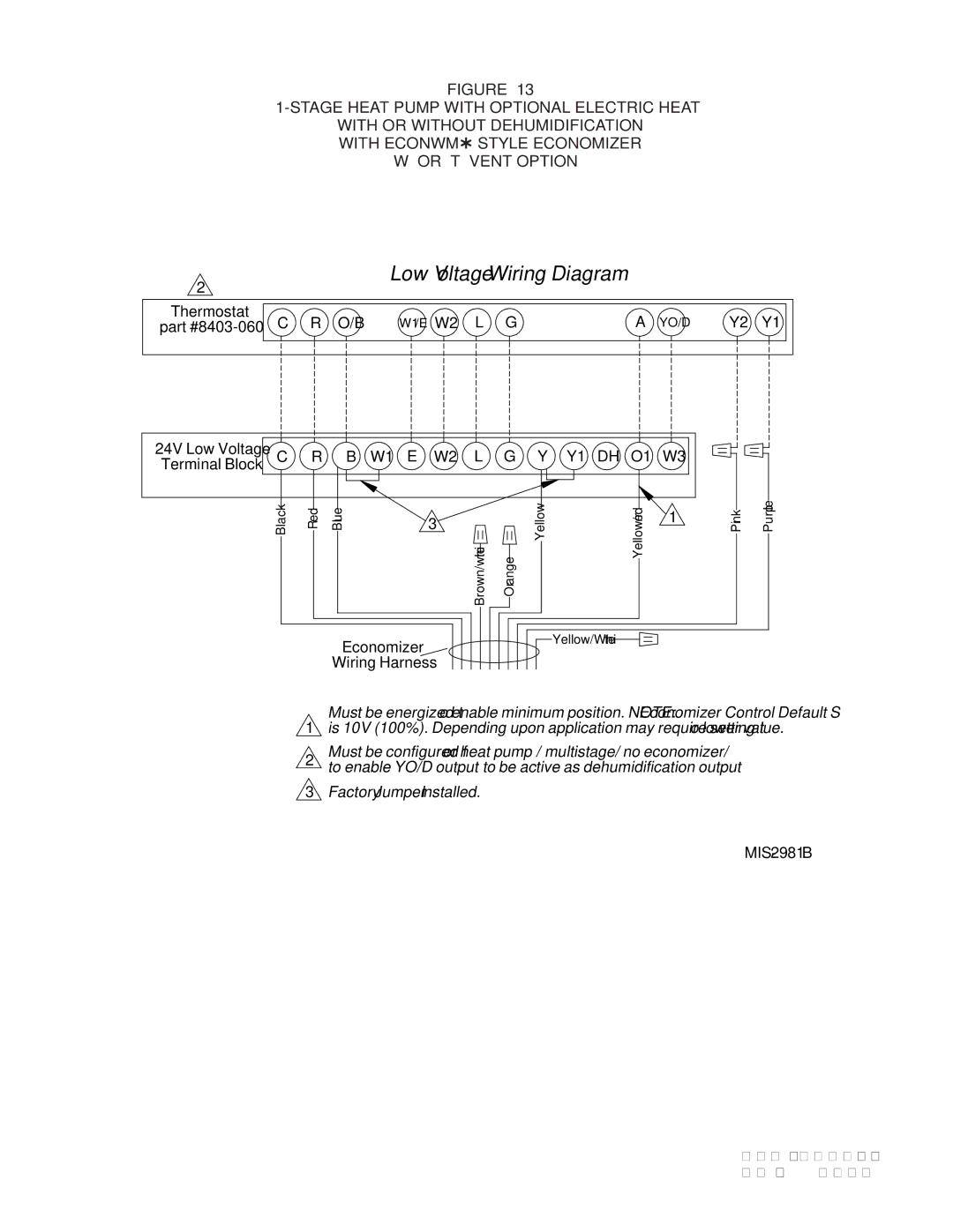
FIGURE 13
WITH OR WITHOUT DEHUMIDIFICATION
WITH ECONWM STYLE ECONOMIZER
“W” OR “T” VENT OPTION
2 |
|
|
| Low Voltage Wiring Diagram |
|
|
|
| ||
|
|
|
|
|
|
|
|
|
| |
Thermostat | C | R | O/B | W1/E W2 | L | G | A | YO/D | Y2 | Y1 |
part | ||||||||||
24V Low Voltage | C | R | B | W1 | E | W2 | L | G | Y | Y1 | DH | O1 | W3 |
|
|
Terminal Block |
|
| |||||||||||||
|
|
|
|
|
| Brown/white |
|
|
|
| Yellow/red |
|
|
| |
| Black | Red | Blue |
|
| 3 | Orange | Yellow |
|
| 1 | Pink | Purple | ||
|
|
|
|
|
|
|
|
|
|
|
|
|
| ||
|
|
|
|
|
|
|
|
|
|
|
|
|
|
|
1
2
3
Economizer | Yellow/White |
| |
Wiring Harness |
|
Must be energized to enable minimum position. NOTE: Economizer Control Default Setting is 10V (100%). Depending upon application may require setting to lower value.
Must be configured for heat pump / multistage/ no economizer/ to enable YO/D output to be active as dehumidification output
Factory Jumper Installed.
Manual |
| |
Page | 17 of 19 | |
