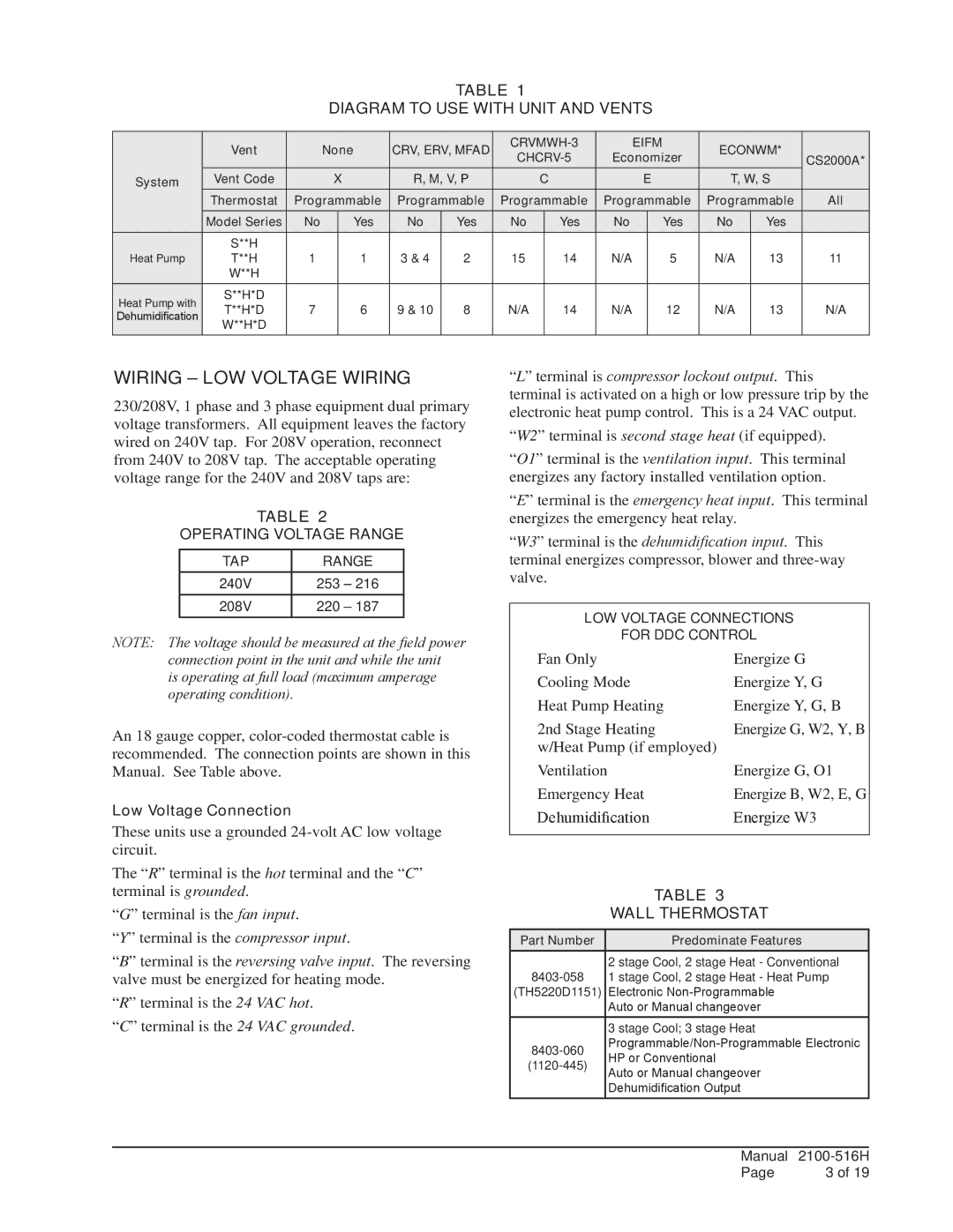
TABLE 1
DIAGRAM TO USE WITH UNIT AND VENTS
| Vent |
| None | CRV, ERV, MFAD |
|
| EIFM | ECONWM* |
| ||||||
|
| Economizer | CS2000A* | ||||||||||||
|
|
|
|
|
|
|
|
| |||||||
System | Vent Code |
| X | R, M, V, P |
| C |
| E | T, W, S |
| |||||
| Thermostat | Programmable | Programmable | Programmable | Programmable | Programmable | All | ||||||||
| Model Series | No |
| Yes | No | Yes | No |
| Yes | No |
| Yes | No | Yes |
|
| S**H |
|
|
|
|
|
|
|
|
|
|
|
|
|
|
Heat Pump | T**H | 1 |
| 1 | 3 & 4 | 2 | 15 |
| 14 | N/A |
| 5 | N/A | 13 | 11 |
| W**H |
|
|
|
|
|
|
|
|
|
|
|
|
|
|
Heat Pump with | S**H*D |
|
|
|
|
|
|
|
|
|
|
|
|
|
|
T**H*D | 7 |
| 6 | 9 & 10 | 8 | N/A |
| 14 | N/A |
| 12 | N/A | 13 | N/A | |
Dehumidification |
|
|
| ||||||||||||
W**H*D |
|
|
|
|
|
|
|
|
|
|
|
|
|
| |
|
|
|
|
|
|
|
|
|
|
|
|
|
|
| |
WIRING – LOW VOLTAGE WIRING
230/208V, 1 phase and 3 phase equipment dual primary voltage transformers. All equipment leaves the factory wired on 240V tap. For 208V operation, reconnect from 240V to 208V tap. The acceptable operating voltage range for the 240V and 208V taps are:
TABLE 2
OPERATING VOLTAGE RANGE
TAP | RANGE |
240V | 253 – 216 |
208V | 220 – 187 |
NOTE: The voltage should be measured at the field power connection point in the unit and while the unit
is operating at full load (maximum amperage operating condition).
An 18 gauge copper,
Low Voltage Connection
These units use a grounded
The “R” terminal is the hot terminal and the “C” terminal is grounded.
“G” terminal is the fan input.
“Y” terminal is the compressor input.
“B” terminal is the reversing valve input. The reversing valve must be energized for heating mode.
“R” terminal is the 24 VAC hot.
“C” terminal is the 24 VAC grounded.
“L” terminal is compressor lockout output. This terminal is activated on a high or low pressure trip by the electronic heat pump control. This is a 24 VAC output.
“W2” terminal is second stage heat (if equipped).
“O1” terminal is the ventilation input. This terminal energizes any factory installed ventilation option.
“E” terminal is the emergency heat input. This terminal energizes the emergency heat relay.
“W3” terminal is the dehumidification input. This terminal energizes compressor, blower and
LOW VOLTAGE CONNECTIONS
FOR DDC CONTROL
Fan Only |
| Energize G | |
Cooling Mode | Energize Y, G | ||
Heat Pump Heating | Energize Y, G, B | ||
2nd Stage Heating | Energize G, W2, Y, B | ||
w/Heat Pump (if employed) | |||
Ventilation |
| Energize G, O1 | |
Emergency Heat | Energize B, W2, E, G | ||
Dehumidification | Energize W3 | ||
|
|
| |
|
| TABLE 3 | |
|
| WALL THERMOSTAT | |
|
|
|
|
Part Number |
|
| Predominate Features |
|
| 2 stage Cool, 2 stage Heat - Conventional | |
| 1 stage Cool, 2 stage Heat - Heat Pump | ||
(TH5220D1151) | Electronic | ||
|
| Auto or Manual changeover | |
|
| 3 stage Cool; 3 stage Heat | |
| |||
| HP or Conventional | ||
| |||
| Auto or Manual changeover | ||
|
| ||
|
| Dehumidification Output | |
|
|
|
|
Manual |
| |
Page | 3 of 19 | |