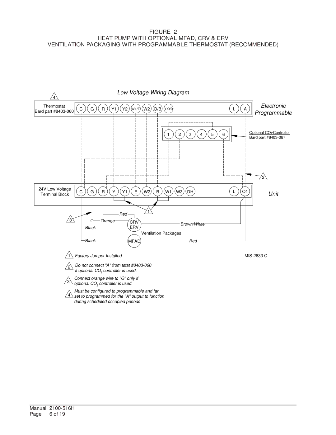
FIGURE 2
HEAT PUMP WITH OPTIONAL MFAD, CRV & ERV
VENTILATION PACKAGING WITH PROGRAMMABLE THERMOSTAT (RECOMMENDED)
4
Low Voltage Wiring Diagram
Thermostat | C | G | R | Y1 | Y2 | W1/E | W2 | O/B | Y O/D | L | A | Electronic | |
Bard part | Programmable | ||||||||||||
|
|
|
|
|
|
|
|
|
|
|
1 | 2 | 3 | 4 | 5 | 6 |
![]()
![]() Optional CO2 Controller
Optional CO2 Controller ![]()
![]() Bard part
Bard part
|
|
|
|
|
|
|
|
|
|
|
|
|
| 2 |
24V Low Voltage | C | G | R | Y | Y1 | E | W2 | B | W1 | W3 | DH | L | O1 | Unit |
Terminal Block | ||||||||||||||
|
|
|
|
| Red |
| 1 |
|
|
|
|
|
|
|
3 |
|
| Orange |
|
|
|
|
|
|
|
|
| ||
|
|
| CRV |
|
|
| Brown/White |
|
|
| ||||
|
| Black |
|
|
| ERV |
|
|
|
|
|
| ||
|
|
|
|
| Ventilation Packages |
|
|
|
| |||||
|
|
|
|
|
|
|
|
|
|
| ||||
|
| Black |
|
|
| MFAD |
|
|
|
| Red |
|
|
|
1 Factory Jumper Installed | ||
|
|
|
2Do not connect "A" from tstat
3Connect orange wire to "G" only if optional CO2 controller is used.
Must be configured to programmable and fan
4 set to programmed for the "A" output to function during scheduled occupied periods
Manual | |
Page | 6 of 19 |