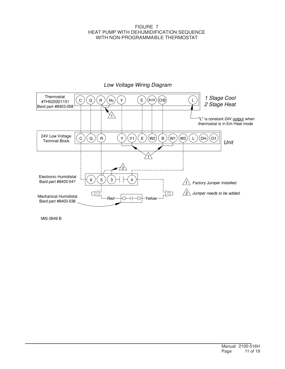
FIGURE 7
HEAT PUMP WITH DEHUMIDIFICATION SEQUENCE
WITH
Low Voltage Wiring Diagram
Thermostat | C | G | R Rc | Y | E | AUX | O/B | ||
#TH5220D1151 | |||||||||
Bard part |
|
|
|
|
|
|
|
| |
|
|
|
| 1 |
|
|
|
| |
24V Low Voltage | C | G | R | Y | Y1 E | W2 | B W1 W3 | ||
Terminal Block | |||||||||
|
|
|
|
|
|
|
| ||
1 ![]()
2
L1 Stage Cool
2 Stage Heat
"L" is constant 24V output when thermostat is in Em Heat mode
L DH O1 Unit
Electronic Humidistat | 6 | 5 | 3 | 4 |
|
| |
Bard part | 1 | Factory Jumper Installed. | |||||
|
|
|
| ||||
Mechanical Humidistat |
|
|
|
| 2 | Jumper needs to be added. | |
|
| Red |
| Yellow |
| ||
Bard part |
|
|
|
| |||
|
|
|
|
|
|
MIS-2649 B
Manual |
| |
Page | 11 of 19 | |
