Adjustment of the Detection Distance
Use the procedure listed below to adjust each detector in order to obtain detection 12" to 16" above the floor. The following adjustments must be made with the detectors in the normal mode (position of J1)
1.To adjust the length of the pattern (from 2’ to 8’), turn the distance potentiometer (cam) clockwise to increase the detection distance.
This can be tested by waving your hand in front of the optic and watching for the red LED to turn on.
NOTE: One notch of the distance adjustment corresponds to approximately 4".
2.Repeat this procedure until the desired distance is achieved.
Function J1: Anti-Masking
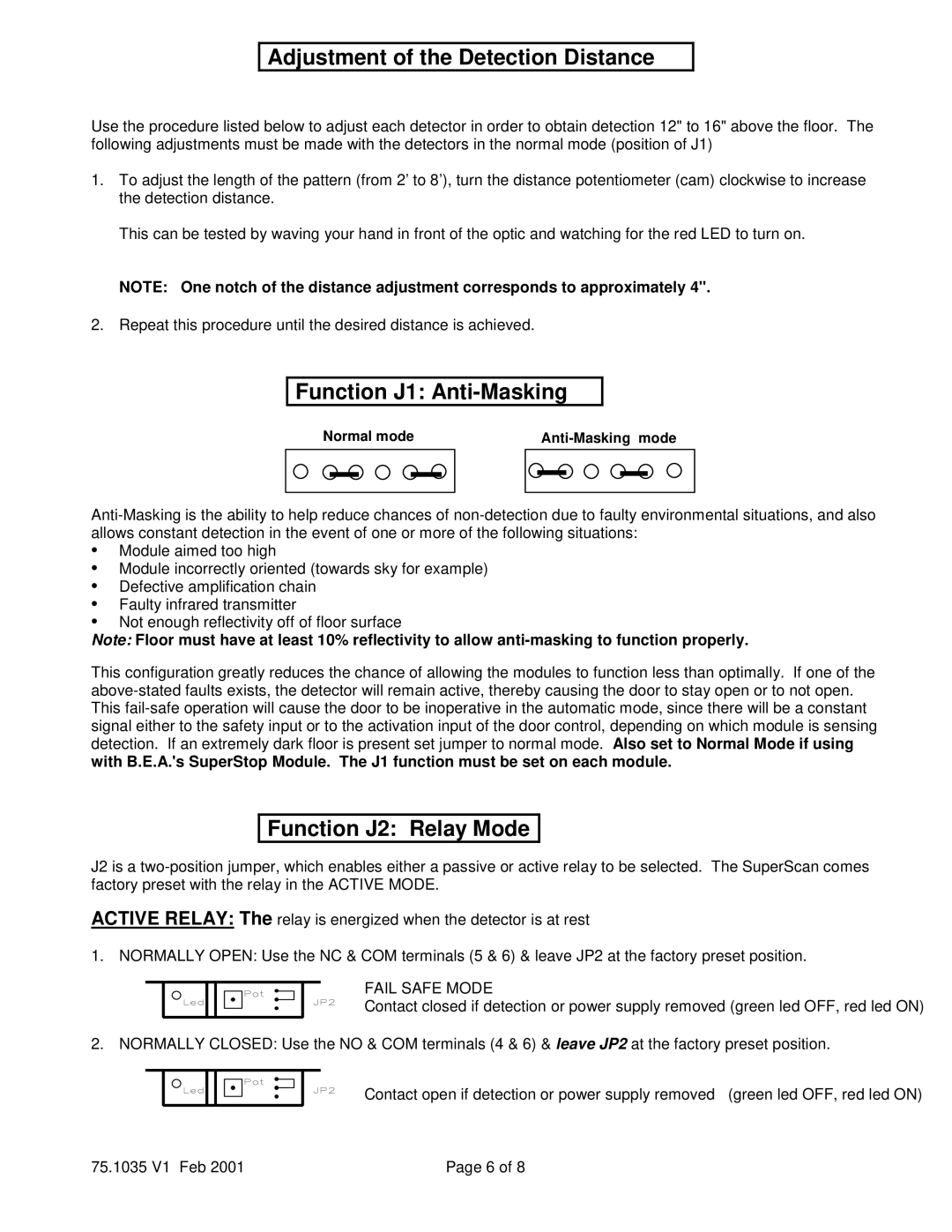
Normal mode |
|
| ||||||||
|
|
|
|
|
|
|
|
|
|
|
|
|
|
|
|
|
|
|
|
|
|
|
|
|
|
|
|
|
|
|
|
|
•Module aimed too high
•Module incorrectly oriented (towards sky for example)
•Defective amplification chain
•Faulty infrared transmitter
•Not enough reflectivity off of floor surface
Note: Floor must have at least 10% reflectivity to allow
This configuration greatly reduces the chance of allowing the modules to function less than optimally. If one of the
Function J2: Relay Mode
J2 is a
ACTIVE RELAY: The relay is energized when the detector is at rest
1. NORMALLY OPEN: Use the NC & COM terminals (5 & 6) & leave JP2 at the factory preset position.
FAIL SAFE MODE
Contact closed if detection or power supply removed (green led OFF, red led ON)
2. NORMALLY CLOSED: Use the NO & COM terminals (4 & 6) & leave JP2 at the factory preset position.
Contact open if detection or power supply removed (green led OFF, red led ON)
75.1035 V1 Feb 2001 | Page 6 of 8 |