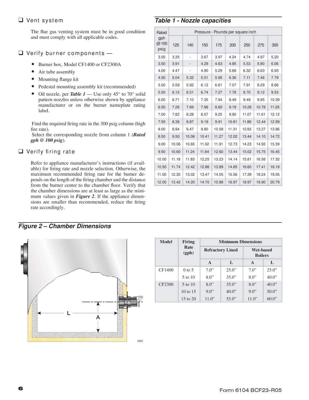
CF2300, CF1400 specifications
Beckett has long been a household name in the heating and oil burner industry, renowned for producing equipment that excels in efficiency, reliability, and innovation. Among its impressive range of products, the CF1400 and CF2300 models stand out as exceptional offerings in the category of oil burners.The Beckett CF1400 is designed for residential applications, delivering a robust performance that satisfies heating needs while minimizing energy consumption. This model is equipped with advanced technology that ensures precise fuel atomization, which translates into cleaner combustion and lower emissions. With adjustable combustion settings, users can optimize the burner for different home heating systems, ensuring peak performance regardless of the conditions.
In contrast, the CF2300 model is engineered for larger residential or light commercial setups. This powerhouse of a burner leverages enhanced fuel delivery systems and cutting-edge control features that allow for efficient operation and maintenance. Its design incorporates a heat exchanger that maximizes heat transfer, resulting in improved energy efficiency. Beckett’s commitment to quality is evident in its use of durable materials, ensuring that these units offer longevity and consistent performance over time.
Both models share several key technologies and characteristics. They are compatible with various heating oil types and can accommodate different fuel tank arrangements. The burners feature adjustable air settings, allowing for easy tuning to achieve optimal combustion performance. The CF1400 and CF2300 are also characterized by quiet operation, ensuring homeowners can enjoy a warm environment without disruptive noise levels.
Safety is paramount in the design of the CF series. Each unit comes equipped with safety controls that prevent overheating and other potential hazards, providing peace of mind to users. Furthermore, installation is user-friendly, and regular maintenance is simplified, reducing service costs and extending the lifespan of the burners.
The Beckett CF1400 and CF2300 models exemplify the brand's dedication to technological advancement and user-centric design. With their combination of efficiency, reliability, and cutting-edge features, these oil burners continue to be preferred choices for homeowners looking to improve their heating systems. Whether for residential or light commercial use, these models provide dependable heating solutions that align with modern energy standards.

