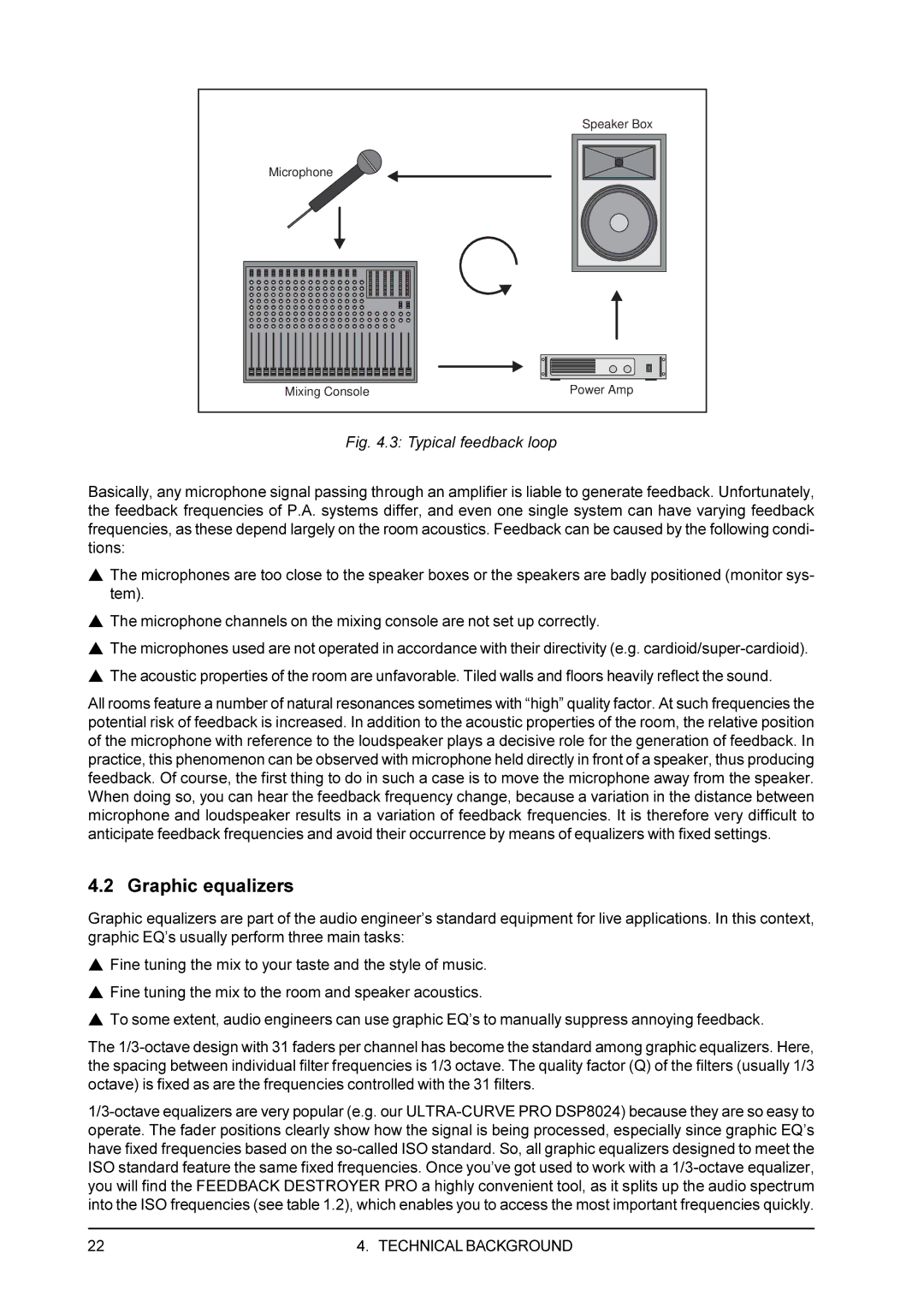
| Speaker Box |
Microphone |
|
Mixing Console | Power Amp |
Fig. 4.3: Typical feedback loop
Basically, any microphone signal passing through an amplifier is liable to generate feedback. Unfortunately, the feedback frequencies of P.A. systems differ, and even one single system can have varying feedback frequencies, as these depend largely on the room acoustics. Feedback can be caused by the following condi- tions:
sThe microphones are too close to the speaker boxes or the speakers are badly positioned (monitor sys- tem).
sThe microphone channels on the mixing console are not set up correctly.
sThe microphones used are not operated in accordance with their directivity (e.g.
sThe acoustic properties of the room are unfavorable. Tiled walls and floors heavily reflect the sound.
All rooms feature a number of natural resonances sometimes with “high” quality factor. At such frequencies the potential risk of feedback is increased. In addition to the acoustic properties of the room, the relative position of the microphone with reference to the loudspeaker plays a decisive role for the generation of feedback. In practice, this phenomenon can be observed with microphone held directly in front of a speaker, thus producing feedback. Of course, the first thing to do in such a case is to move the microphone away from the speaker. When doing so, you can hear the feedback frequency change, because a variation in the distance between microphone and loudspeaker results in a variation of feedback frequencies. It is therefore very difficult to anticipate feedback frequencies and avoid their occurrence by means of equalizers with fixed settings.
4.2 Graphic equalizers
Graphic equalizers are part of the audio engineer’s standard equipment for live applications. In this context, graphic EQ’s usually perform three main tasks:
sFine tuning the mix to your taste and the style of music.
sFine tuning the mix to the room and speaker acoustics.
sTo some extent, audio engineers can use graphic EQ’s to manually suppress annoying feedback.
The
22 | 4. TECHNICAL BACKGROUND |