On
In Single Shot mode the filter will not release a setting which has been achieved until you manually change it. This is particularly useful with problems at discrete frequencies like turntable resonances and fixed micro- phone and monitor positions. If feedback is detected the filter will deal with that frequency and the status of that filter will change to Locked (LO). It will only widen its bandwidth or increase the attenuation but it will not release that setting to destroy a new feedback. In Auto mode the oldest filter will be released to destroy a new feedback.
1.4 Control elements
E
Fig. 1.1: FEEDBACK DESTROYER PRO front panel
The BEHRINGER FEEDBACK DESTROYER PRO is equipped with ten parameters keys, one jog wheel (rotary control) which is used to alter the selected parameter or preset and a numeric LED display. Each of the 24 filters has one LED assigned to it, which informs you about the status of the filter. By means of an
1.4.1 Front panel control elements
1
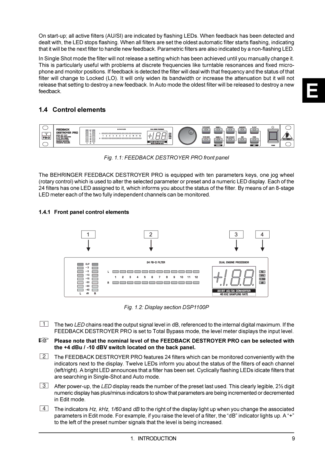
Fig. 1.2: Display section DSP1100P
The two LED chains read the output signal level in dB, referenced to the internal digital maximum. If the FEEDBACK DESTROYER PRO is set to Total Bypass mode, the level meter displays the input level.
+Please note that the nominal level of the FEEDBACK DESTROYER PRO can be selected with the +4 dBu /
2
The FEEDBACK DESTROYER PRO features 24 filters which can be monitored conveniently with the indicators next to the display. Twelve LEDs inform you about the status of the filters of each channel (left/right). A bright LED announces that a filter has been set. Cyclically flashing LEDs idicate filters that are searching in
3
After
4
The indicators Hz, kHz, 1/60 and dB to the right of the display light up when you change the associated parameters in Edit mode. For example, if you raise the level of a filter, the “dB” indicator lights up. A “+” to the left of the preset number signals that the level is being increased.
1. INTRODUCTION | 9 |