Manuals
/
Behringer
/
Home Audio
/
Stereo Amplifier
Behringer
DSP8024
user manual
RTA mode
Models:
DSP8024
1
28
36
36
Download
36 pages
40.7 Kb
25
26
27
28
29
30
31
32
Page 28
Image 28
Page 27
Page 29
Page 28
Image 28
Page 27
Page 29
Contents
ENGLISH
User’s Manual
ULTRA-CURVE PRO DSP8024
SAFETY INSTRUCTIONS
FOREWORD
ULTRA-CURVEPRO
TABLE OF CONTENTS
1.1 The design concept
1. INTRODUCTION
1.2 Before you begin
1.3 Control elements
2. OPERATION
2.1.1 Operating the graphic equalizer
2.1 EQ mode
2.1.2 The level meter
2.1.3 The FEEDBACK DESTROYER
Program administration
2.1.4 Delay
2.1.5 Equalizer editing
a Loading programs
a Resetting all faders to zero
b Inverting the current settings
b Saving programs
c Additive and subtractive editing of programs
Channel switching
2.1.6 EQ setup
Comparison functions
STEREOLINK ON
2.2 Real time analyzer
SHELVING SLOPE
LIMIT THRESHOLD
LIMIT RELEASE
2.2.1 Program administration
a Loading measurements
b Storing measurements
c Transferring measurements to the equalizer
2.2.5 RTA setup
SINE f
2.3 AUTO-Qfunction
LEVEL
2.4 General setup
VIEWING ANGLE
RTA LOCK
SECURITY
PROTECT MEM
3. APPLICATIONS
MIDI
CHANNEL
SND MEMORY DUMP
ULTRA-CURVEPRO DSP8024
ULTRA-CURVEPRO DSP8024
3.4 The ULTRA-CURVEPRO as a delay unit
ULTRA-CURVEPRO DSP8024
4. “TRUE RESPONSE” CHARACTERISTIC
5. ULTRA-CURVEPRO STRUCTURE
5.1 Hardware
ULTRA-CURVEPRO DSP8024
5.2 EQ mode
5. ULTRA-CURVEPRO STRUCTURE
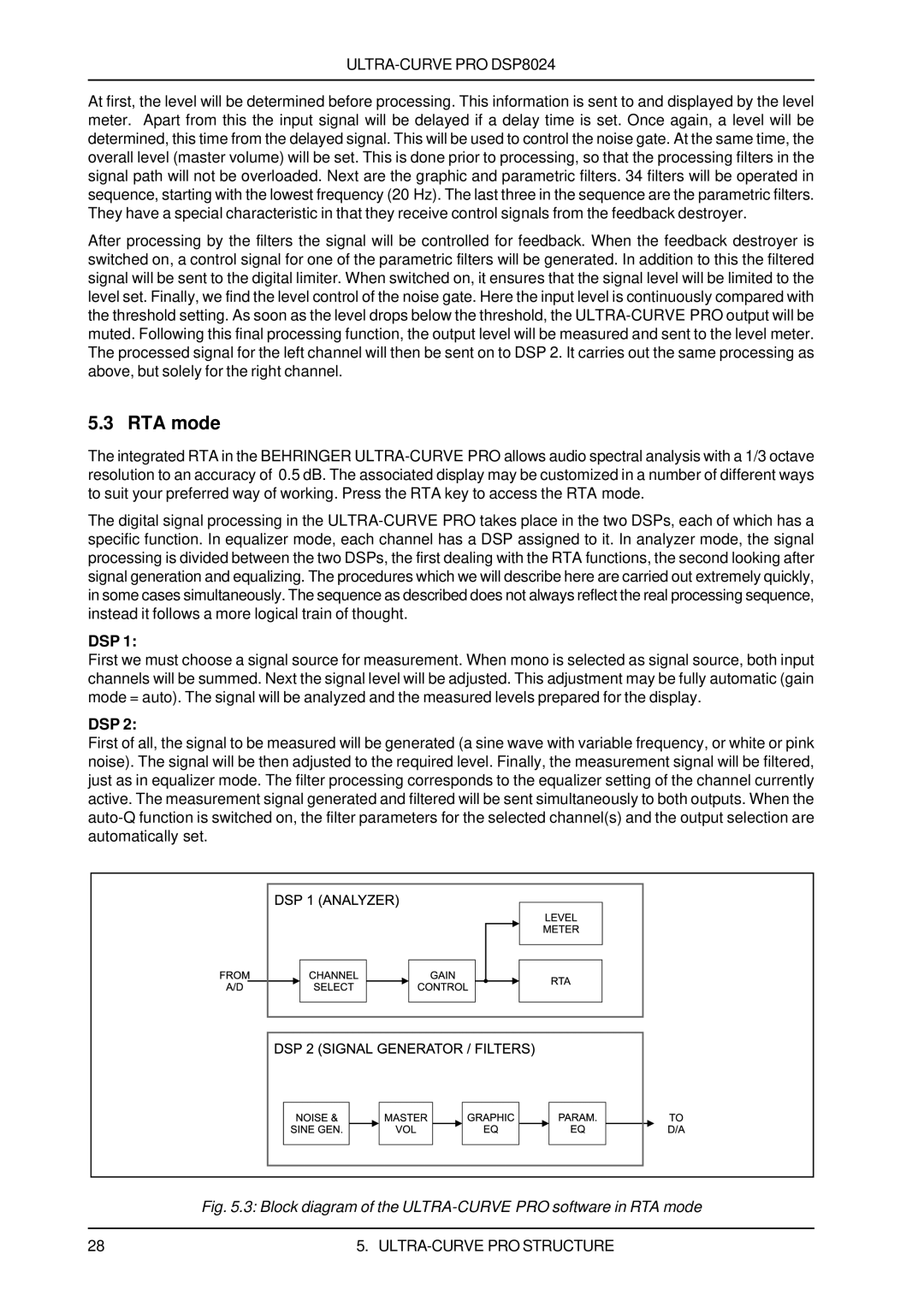
5.3 RTA mode
6.1 Mains connection
6. INSTALLATION
6.2 Audio connections
ULTRA-CURVEPRO DSP8024
7.2 Changing the memory protect battery
7. APPENDIX
6.4 MIDI connections
7.1 AES8024 option
7.3 MIDI implementation
7.4 Software
8. TECHNICAL SPECIFICATIONS
Power supply
Digital delay
Level meter
Noise gate
9.WARRANTY
§1 WARRANTY CARD/ONLINE REGISTRATION
§2 WARRANTY
§3 RETURN AUTHORIZATION NUMBER
Top
Page
Image
Contents