MULTIGATE PRO XR4400
6
This “traffic light” LED chain shows the current operating mode of the unit: the “+” LED (red) indicates that the sidechain signal is below the threshold, the HOLD LED (yellow) informs you that the hold circuit/release process has been activated, while the
7
The HOLD control determines the delay applied to the starting point of the release process, after the signal has dropped below the threshold. The setting range is 0 to 4 seconds.
+The HOLD control is enabled in GATE mode only!
8
+
9
10
11
The RELEASE control determines the time of the release process. This process begins after the end of the hold phase and ends when the gain reduction adjusted with the RANGE control is achieved. The setting range of the RELEASE control is from 0.05 to 4 seconds.
The RELEASE control is enabled in GATE mode only!
The MODE switch is used to set the operating mode of the respective channel. When the switch is out, the corresponding section works as an
The RANGE/RATIO control performs a dual function: depending on the position of the MODE
switch (i.e. depending on the operating mode of the unit: gate or expander), the RANGE/RATIO control determines the maximum amount of gain reduction or the expansion curve. In gate mode, this control adjusts the RANGE determining the amount of maximum gain reduction from 0 dB to
The
12
When you press the COUPLE switch, this channel is automatically configured as a “slave” channel. Its left neighbor becomes the “master” now controlling both channels in all their parameters.
4.2 The rear panel elements
13
14
15
16
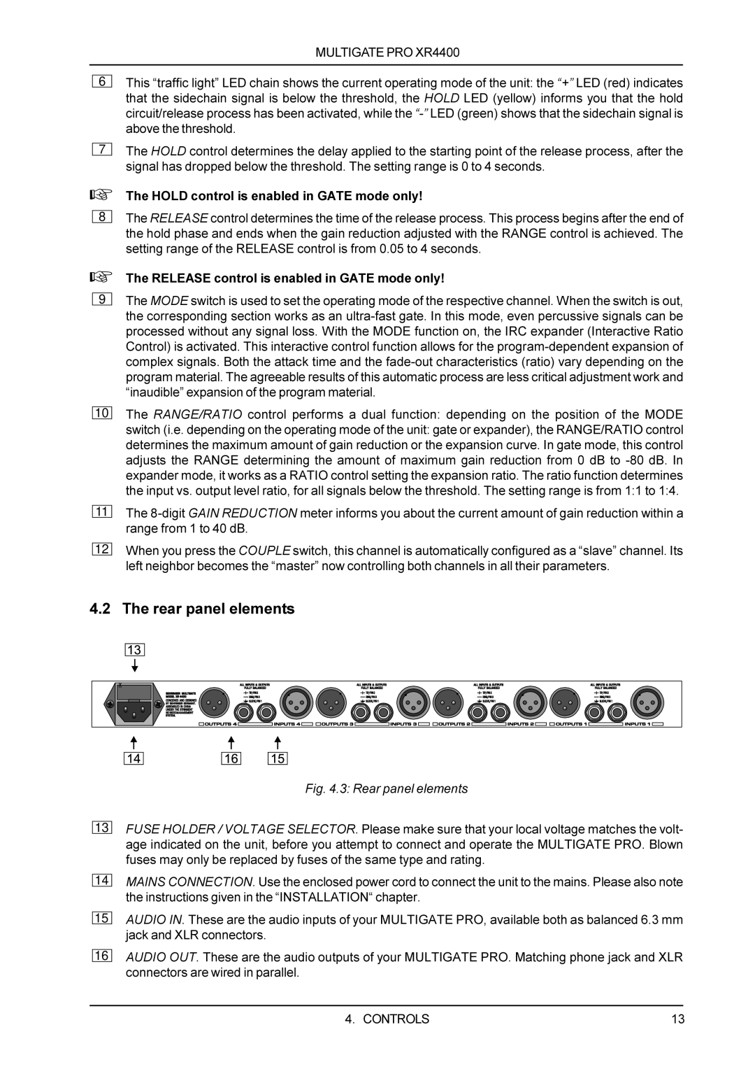
Fig. 4.3: Rear panel elements
FUSE HOLDER / VOLTAGE SELECTOR. Please make sure that your local voltage matches the volt- age indicated on the unit, before you attempt to connect and operate the MULTIGATE PRO. Blown fuses may only be replaced by fuses of the same type and rating.
MAINS CONNECTION. Use the enclosed power cord to connect the unit to the mains. Please also note the instructions given in the “INSTALLATION“ chapter.
AUDIO IN. These are the audio inputs of your MULTIGATE PRO, available both as balanced 6.3 mm jack and XLR connectors.
AUDIO OUT. These are the audio outputs of your MULTIGATE PRO. Matching phone jack and XLR connectors are wired in parallel.
4. CONTROLS | 13 |