OIL
SEPARATOR
DESICCANT
BED
PURGE
ORIFICE
PURGE
CONTROLVOLUME
PORT
PURGE |
| |
CONTROL | SUPPLY | |
LINE | ||
PORT | ||
|
GOVERNOR |
|
|
| DELIVERY |
|
|
|
| |
|
|
|
| CHECK VALVE |
|
|
|
| (OLD STYLE |
|
|
| PURGE | SHOWN) |
|
| TURBO | DISCHARGE | |
COMPRESSOR | ENGINE | VALVE | ||
| TURBO | CUTOFF | EXHAUST | PORT |
|
| VALVE |
|
|
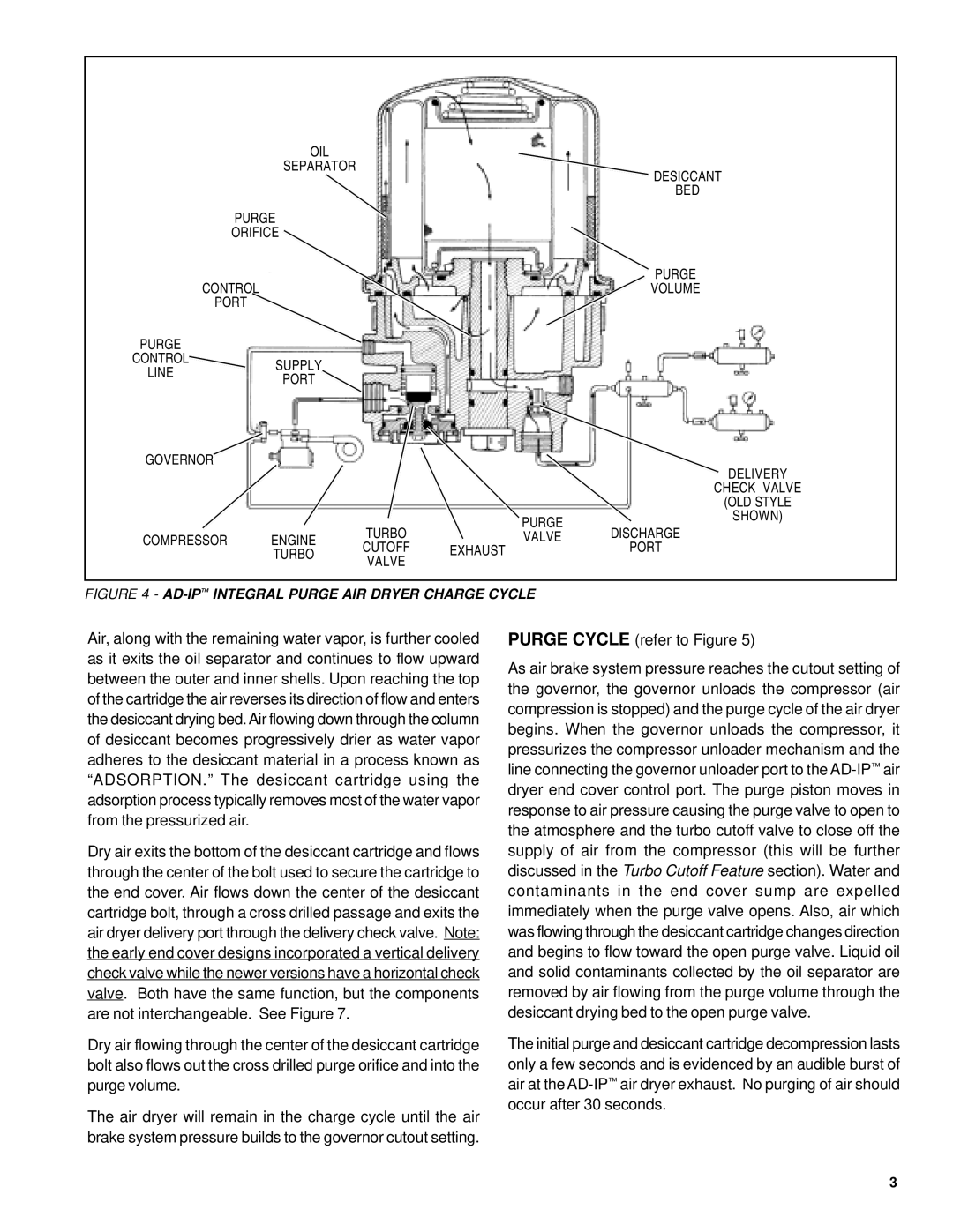
FIGURE 4 - AD-IP™ INTEGRAL PURGE AIR DRYER CHARGE CYCLE
Air, along with the remaining water vapor, is further cooled as it exits the oil separator and continues to flow upward between the outer and inner shells. Upon reaching the top of the cartridge the air reverses its direction of flow and enters the desiccant drying bed.Air flowing down through the column of desiccant becomes progressively drier as water vapor adheres to the desiccant material in a process known as “ADSORPTION.” The desiccant cartridge using the adsorption process typically removes most of the water vapor from the pressurized air.
Dry air exits the bottom of the desiccant cartridge and flows through the center of the bolt used to secure the cartridge to the end cover. Air flows down the center of the desiccant cartridge bolt, through a cross drilled passage and exits the air dryer delivery port through the delivery check valve. Note: the early end cover designs incorporated a vertical delivery check valve while the newer versions have a horizontal check valve. Both have the same function, but the components are not interchangeable. See Figure 7.
Dry air flowing through the center of the desiccant cartridge bolt also flows out the cross drilled purge orifice and into the purge volume.
The air dryer will remain in the charge cycle until the air brake system pressure builds to the governor cutout setting.
PURGE CYCLE (refer to Figure 5)
As air brake system pressure reaches the cutout setting of the governor, the governor unloads the compressor (air compression is stopped) and the purge cycle of the air dryer begins. When the governor unloads the compressor, it pressurizes the compressor unloader mechanism and the line connecting the governor unloader port to the
The initial purge and desiccant cartridge decompression lasts only a few seconds and is evidenced by an audible burst of air at the
3