DELIVERY
CHECK
VALVE
GOVERNOR (CLOSED)
UNLOADER
PORT
PURGE
INLET CONTROL
PORT CHANNEL (IN) ![]()
TURBO
CUTOFF EXHAUST
VALVE PURGE (CLOSED) VALVE
(OPEN)
ENGINE
TURBO
![]() COMPRESSOR
COMPRESSOR
GOVERNOR SIGNALS AIR
COMPRESSOR TO SUSPEND
COMPRESSED AIR SUPPLY
TO
SAFETY
VALVE
DESICCANT
BED
OIL
SEPARATOR
PURGE
ORIFICE
PURGE
RESERVOIR
PRESSURE PROTECTION
VALVES
A
B C D
PRIMARY | SECONDARY |
PORT | RESERVOIR |
(PRI) | AUXILIARY PORTS |
| (TO ACCESSORIES) |
| PURGE |
| RESERVOIR |
| DRAIN VALVE |
PRIMARY
![]() RESERVOIR
RESERVOIR
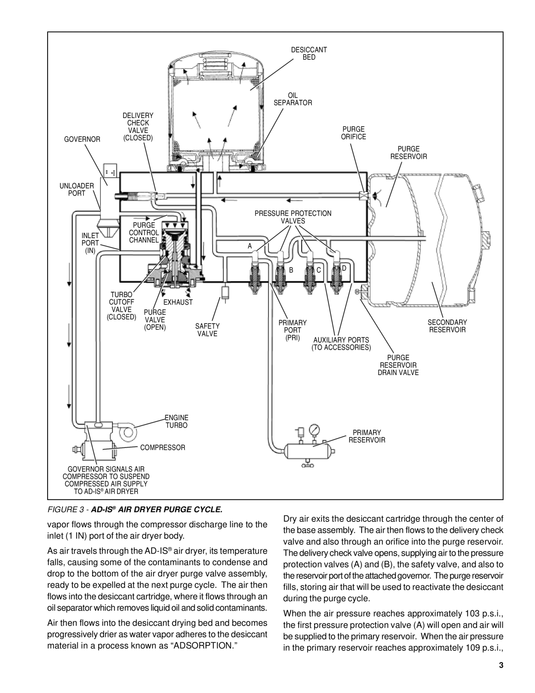
FIGURE 3 - AD-IS® AIR DRYER PURGE CYCLE.
vapor flows through the compressor discharge line to the inlet (1 IN) port of the air dryer body.
As air travels through the
Air then flows into the desiccant drying bed and becomes progressively drier as water vapor adheres to the desiccant material in a process known as “ADSORPTION.”
Dry air exits the desiccant cartridge through the center of the base assembly. The air then flows to the delivery check valve and also through an orifice into the purge reservoir. The delivery check valve opens, supplying air to the pressure protection valves (A) and (B), the safety valve, and also to the reservoir port of the attached governor. The purge reservoir fills, storing air that will be used to reactivate the desiccant during the purge cycle.
When the air pressure reaches approximately 103 p.s.i., the first pressure protection valve (A) will open and air will be supplied to the primary reservoir. When the air pressure in the primary reservoir reaches approximately 109 p.s.i.,
3