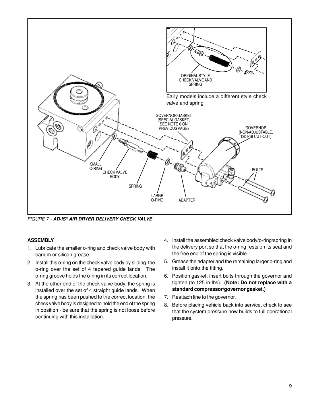
ORIGINAL STYLE
CHECK VALVE AND
SPRING
Early models include a different style check valve and spring
GOVERNOR GASKET
(SPECIAL GASKET,
SEE NOTE 6 ON
PREVIOUS PAGE)GOVERNOR
130 PSI
SMALL |
|
|
CHECK VALVE | BOLTS | |
| ||
|
| |
| BODY |
|
SPRING
LARGE
FIGURE 7 - AD-IS® AIR DRYER DELIVERY CHECK VALVE
ASSEMBLY
1.Lubricate the smaller
2.Install this
3.At the other end of the check valve body, the spring is installed over the set of 4 straight guide lands. When the spring has been pushed to the correct location, the check valve body is designed to hold the end of the spring in position - be sure that the spring is not loose before continuing with this installation.
4.Install the assembled check valve
5.Grease the adapter and the remaining larger
6.Position gasket, insert bolts through the governor and tighten (to 125
7.Reattach line to the governor.
8.Before placing vehicle back into service, check to see that the system pressure now builds to full operational pressure.
9