DESCRIPTION
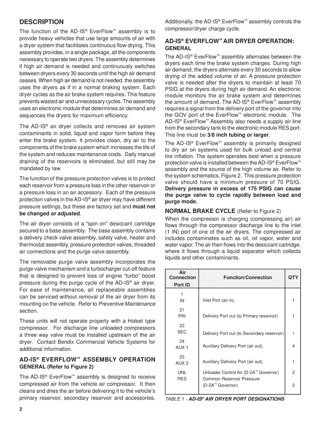
The function of the AD-IS®EverFlow™ assembly is to provide heavy vehicles that use large amounts of air with a dryer system that facilitates continuous flow drying. This assembly provides, in a single package, all the components necessary to operate two dryers. The assembly determines if high air demand is needed and continuously switches between dryers every 30 seconds until the high air demand ceases. When high air demand is not needed, the assembly uses the dryers as if in a normal braking system. Each dryer cycles as the air brake system requires. This feature prevents wasted air and unnecessary cycles. The assembly uses an electronic module that determines air demand and sequences the dryers for maximum efficiency.
The AD-IS®air dryer collects and removes air system contaminants in solid, liquid and vapor form before they enter the brake system. It provides clean, dry air to the components of the brake system which increases the life of the system and reduces maintenance costs. Daily manual draining of the reservoirs is eliminated, but still may be mandated by law.
The function of the pressure protection valves is to protect each reservoir from a pressure loss in the other reservoir or a pressure loss in an air accessory. Each of the pressure protection valves in the AD-IS®air dryer may have different pressure settings, but these are factory set and must not be changed or adjusted.
The air dryer consists of a “spin on” desiccant cartridge secured to a base assembly. The base assembly contains a delivery check valve assembly, safety valve, heater and thermostat assembly, pressure protection valves, threaded air connections and the purge valve assembly.
The removable purge valve assembly incorporates the purge valve mechanism and a turbocharger cut-off feature that is designed to prevent loss of engine “turbo” boost pressure during the purge cycle of the AD-IS®air dryer. For ease of maintenance, all replaceable assemblies can be serviced without removal of the air dryer from its mounting on the vehicle. Refer to Preventive Maintenance section.
These units will not operate properly with a Holset type compressor. For discharge line unloaded compressors a three way valve must be installed upstream of the air dryer. Contact Bendix Commercial Vehicle Systems for additional information.
AD-IS®EVERFLOW™ ASSEMBLY OPERATION
GENERAL (Refer to Figure 2)
The AD-IS®EverFlow™ assembly is designed to receive compressed air from the vehicle air compressor. It then cleans and dries the air before delivering it to the vehicle’s primary reservoir, secondary reservoir and accessories.
Additionally, the AD-IS®EverFlow™ assembly controls the compressor/dryer charge cycle.
AD-IS®EVERFLOW™ AIR DRYER OPERATION:
GENERAL
The AD-IS®EverFlow™ assembly alternates between the dryers each time the brake system charges. During high air demand, the dryers alternate every 30 seconds to allow drying of the added volume of air. A pressure protection valve is needed after the dryers to maintain at least 70 PSIG at the dryers during high air demand. An electronic module monitors the air brake system and determines the amount of demand. The AD-IS®EverFlow™ assembly requires a signal from the delivery port of the governor into the GOV port of the EverFlow™ electronic module. The AD-IS®EverFlow™ Assembly also needs a supply air line from the secondary tank to the electronic module RES port.
This line must be 3/8 inch tubing or larger.
The AD-IS®EverFlow™ assembly is primarily designed to dry air on systems used for bulk unload and central tire inflation. The system operates best when a pressure protection valve is installed between the AD-IS®EverFlow™ assembly and the source of the high volume air. Refer to the system schematics, Figure 2. This pressure protection valve should have a minimum pressure of 70 PSIG.
Delivery pressure in excess of 175 PSIG can cause the purge valve to cycle rapidly between load and purge mode.
NORMAL BRAKE CYCLE (Refer to Figure 2)
When the compressor is charging (compressing air) air flows through the compressor discharge line to the inlet (1 IN) port of one of the air dryers. The compressed air includes contaminates such as oil, oil vapor, water and water vapor. The air then flows into the desiccant cartridge, where it flows through a liquid separator which collects liquids and other contaminants.
Air | Function/Connection | QTY |
Connection |
Port ID | | |
1 | Inlet Port (air in). | 1 |
IN |
21 | Delivery Port out (to Primary reservoir) | 1 |
PRI |
22 | | |
SEC | Delivery Port out (to Secondary reservoir) | 1 |
24 | Auxiliary Delivery Port (air out). | 4 |
AUX 1 |
23 | Auxiliary Delivery Port (air out). | 1 |
AUX 2 |
UNL | Unloader Control Air (D-2A™Governor) | 2 |
RES | Common Reservoir Pressure | |
| (D-2A™Governor) | 2 |
| | |
TABLE 1 - AD-IS®AIR DRYER PORT DESIGNATIONS
