| Governor |
|
|
| EverFlow™ Module |
| |
|
|
|
|
|
| ||
|
| CON |
| GOV | RES |
| |
|
|
|
|
| |||
| CON |
|
|
|
| 3/8" |
|
|
|
|
|
|
|
| |
Schrader |
|
|
|
|
|
|
|
Valve |
|
| RES | SEC | CON | CON |
|
| 1/4" |
|
| Primary | |||
From | Supply | CON | PRI |
| 1/2" | ||
|
|
| Reservoir | ||||
Engine |
| IN |
|
|
| 1/2" | |
IN | CON |
|
|
|
|
| |
| OUT |
|
|
|
| Secondary | |
|
|
|
|
|
| ||
|
|
|
|
| EFMIS® | Check | |
|
|
|
|
| Reservoir | ||
|
|
|
|
|
|
| |
|
|
|
|
| - | Valve |
|
|
|
|
|
| AD | Supply |
|
|
|
|
| Accessories |
|
| |
Compressor |
|
|
| IN |
| ||
|
|
| Dryer OUT | CON | Manual Valve | ||
|
|
|
|
| Pressure |
| |
|
| CON |
|
|
| Protection Valve |
|
|
|
|
|
| (Optional) |
| |
EverFlow™ | Bulk Offload CTI | |
IN | ||
CTI System | ||
|
Bulk Tanker
Compressor
OUT Discharge Line
Unloader Valve
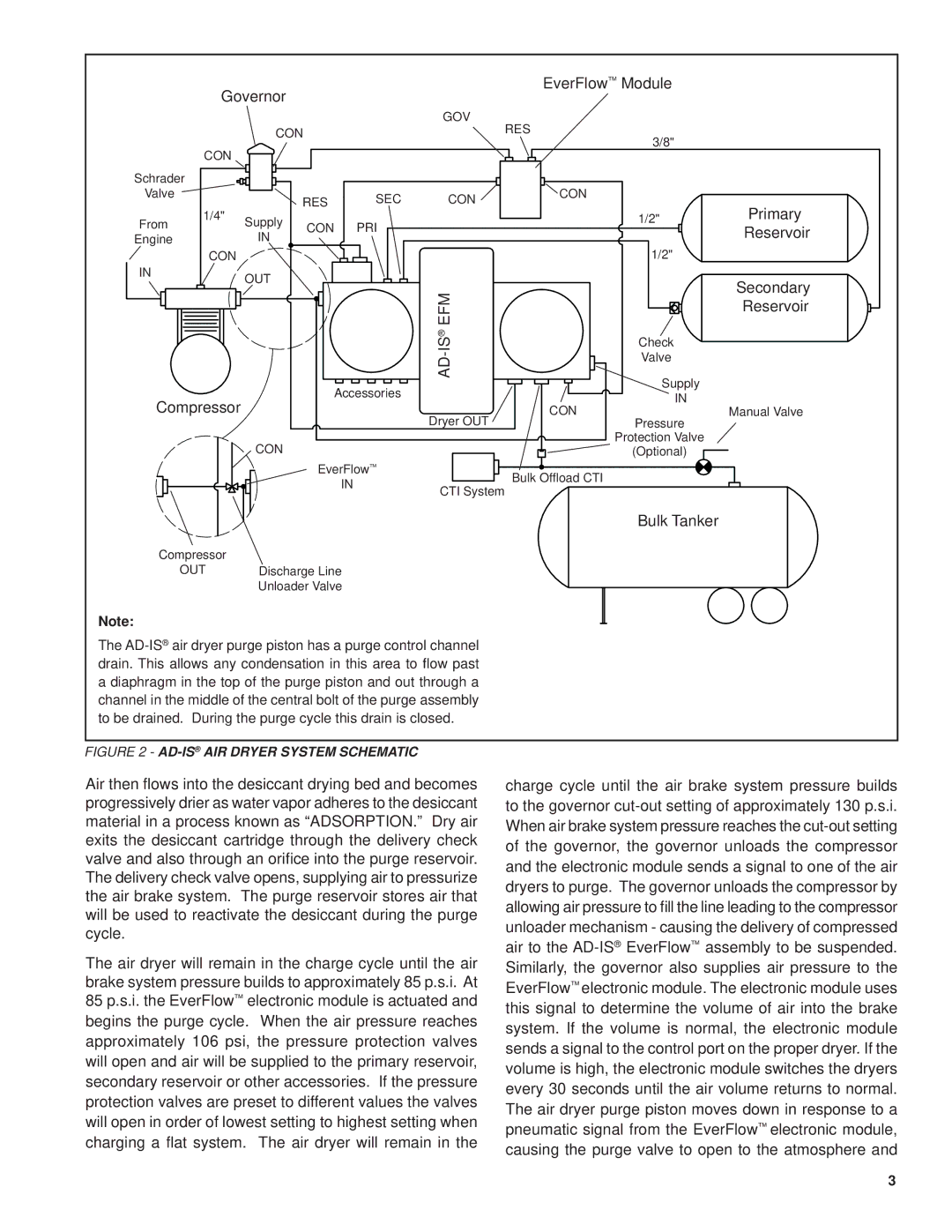
Note:
The
FIGURE 2 - AD-IS® AIR DRYER SYSTEM SCHEMATIC
Air then flows into the desiccant drying bed and becomes progressively drier as water vapor adheres to the desiccant material in a process known as “ADSORPTION.” Dry air exits the desiccant cartridge through the delivery check valve and also through an orifice into the purge reservoir. The delivery check valve opens, supplying air to pressurize the air brake system. The purge reservoir stores air that will be used to reactivate the desiccant during the purge cycle.
The air dryer will remain in the charge cycle until the air brake system pressure builds to approximately 85 p.s.i. At 85 p.s.i. the EverFlow™ electronic module is actuated and begins the purge cycle. When the air pressure reaches approximately 106 psi, the pressure protection valves will open and air will be supplied to the primary reservoir, secondary reservoir or other accessories. If the pressure protection valves are preset to different values the valves will open in order of lowest setting to highest setting when charging a flat system. The air dryer will remain in the
charge cycle until the air brake system pressure builds to the governor
3