Miscellaneous Troubleshooting
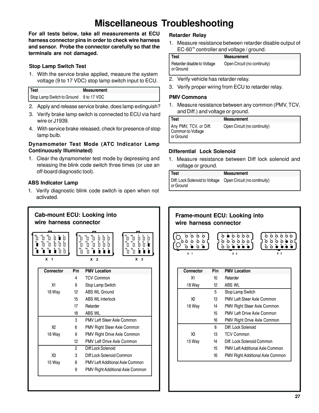
For all tests below, take all measurements at ECU harness connector pins in order to check wire harness and sensor. Probe the connector carefully so that the terminals are not damaged.
Stop Lamp Switch Test
1.With the service brake applied, measure the system voltage (9 to 17 VDC) stop lamp switch input to ECU.
TestMeasurement
Stop Lamp Switch to Ground 9 to 17 VDC
2.Apply and release service brake, does lamp extinguish?
3.Verify brake lamp switch is connected to ECU via hard wire or J1939.
4.With service brake released, check for presence of stop lamp bulb.
Dynamometer Test Mode (ATC Indicator Lamp Continuously Illuminated)
1.Clear the dynamometer test mode by depressing and releasing the blink code switch three times (or use an
ABS Indicator Lamp
1.Verify diagnostic blink code switch is open when not activated.
Retarder Relay
1.Measure resistance between retarder disable output of
Test | Measurement |
Retarder disable to Voltage | Open Circuit (no continuity) |
or Ground |
|
|
|
2.Verify vehicle has retarder relay.
3.Verify proper wiring from ECU to retarder relay.
PMV Commons
1.Measure resistance between any common (PMV, TCV, and Diff.) and voltage or ground.
Test | Measurement |
Any PMV, TCV, or Diff. | Open Circuit (no continuity) |
Common to Voltage |
|
or Ground |
|
|
|
Differential Lock Solenoid
1.Measure resistance between Diff lock solenoid and voltage or ground.
TestMeasurement
Diff. Lock Solenoid to Voltage Open Circuit (no continuity) or Ground
Cab-mount ECU: Looking into wire harness connector
Connector | Pin | PMV Location |
| 4 | TCV Common |
X1 | 9 | Stop Lamp Switch |
18 Way | 12 | ABS WL Ground |
| 15 | ABS WL Interlock |
| 17 | Retarder |
| 18 | ABS WL |
| 3 | PMV Left Steer Axle Common |
X2 | 6 | PMV Right Steer Axle Common |
18 Way | 9 | PMV Right Drive Axle Common |
| 12 | PMV Left Drive Axle Common |
|
|
|
| 2 | Diff Lock Solenoid |
X3 | 3 | Diff Lock Solenoid Common |
15 Way | 6 | PMV Left Additional Axle Common |
| 9 | PMV Right Additional Axle Common |
|
|
|
Frame-mount ECU: Looking into wire harness connector
Connector | Pin | PMV Location |
X1 | 10 | Retarder |
18 Way | 12 | ABS WL |
|
|
|
| 5 | Stop Lamp Switch |
X2 | 13 | PMV Left Steer Axle Common |
18 Way | 14 | PMV Right Steer Axle Common |
| 15 | PMV Left Drive Axle Common |
| 16 | PMV Right Drive Axle Common |
|
|
|
| 8 | Diff. Lock Solenoid |
X3 | 13 | TCV Common |
15 Way | 14 | Diff. Lock Solenoid Common |
| 15 | PMV Left Additional Axle Common |
| 16 | PMV Right Additional Axle Common |
|
|
|
27
