AIR INLET
COMPENSATING TILT
VALVE UNSEALED
POSITION
HYDRAULIC
FLUID PORT
PISTON
POSITION
RETURN SPRING
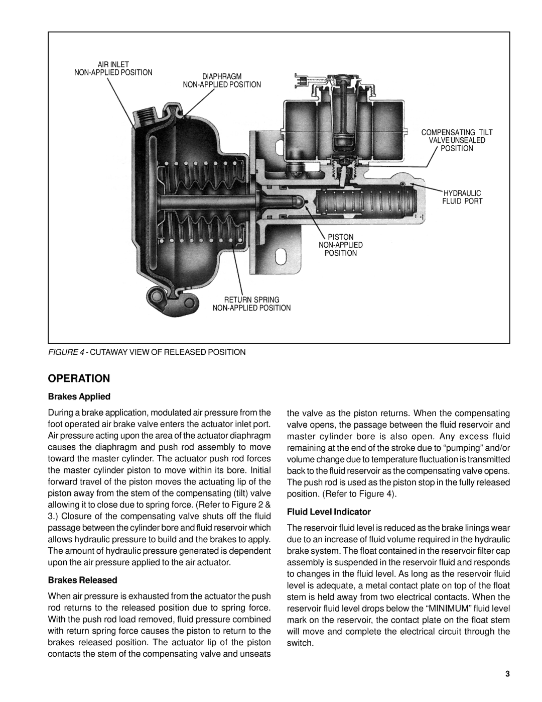
FIGURE 4 - CUTAWAY VIEW OF RELEASED POSITION
OPERATION
Brakes Applied
During a brake application, modulated air pressure from the foot operated air brake valve enters the actuator inlet port. Air pressure acting upon the area of the actuator diaphragm causes the diaphragm and push rod assembly to move toward the master cylinder. The actuator push rod forces the master cylinder piston to move within its bore. Initial forward travel of the piston moves the actuating lip of the piston away from the stem of the compensating (tilt) valve allowing it to close due to spring force. (Refer to Figure 2 & 3.) Closure of the compensating valve shuts off the fluid passage between the cylinder bore and fluid reservoir which allows hydraulic pressure to build and the brakes to apply. The amount of hydraulic pressure generated is dependent upon the air pressure applied to the air actuator.
Brakes Released
When air pressure is exhausted from the actuator the push rod returns to the released position due to spring force. With the push rod load removed, fluid pressure combined with return spring force causes the piston to return to the brakes released position. The actuator lip of the piston contacts the stem of the compensating valve and unseats
the valve as the piston returns. When the compensating valve opens, the passage between the fluid reservoir and master cylinder bore is also open. Any excess fluid remaining at the end of the stroke due to “pumping” and/or volume change due to temperature fluctuation is transmitted back to the fluid reservoir as the compensating valve opens. The push rod is used as the piston stop in the fully released position. (Refer to Figure 4).
Fluid Level Indicator
The reservoir fluid level is reduced as the brake linings wear due to an increase of fluid volume required in the hydraulic brake system. The float contained in the reservoir filter cap assembly is suspended in the reservoir fluid and responds to changes in the fluid level. As long as the reservoir fluid level is adequate, a metal contact plate on top of the float stem is held away from two electrical contacts. When the reservoir fluid level drops below the “MINIMUM” fluid level mark on the reservoir, the contact plate on the float stem will move and complete the electrical circuit through the switch.
3