®
 SD-11-1326
SD-11-1326Bendix® AH-1B™ Air Hydraulic Intensifier
|
| ELECTRICAL FLUID |
|
| |
|
| LEVEL INDICATOR |
|
| |
|
| CONNECTION |
|
| |
|
|
| BRAKE FLUID | ||
| RESERVOIR |
| RESERVOIR | ||
| CAP |
|
| AIR | |
|
|
|
| ||
|
|
|
| INLET | |
|
|
|
| PORT | |
|
|
|
| ACTUATOR | |
| BRAKE FLUID |
|
|
|
|
| DELIVERY PORT |
|
|
|
|
|
| MASTER |
|
|
|
|
| CYLINDER |
|
|
|
|
|
|
| MOUNTING | |
|
|
|
| BRACKET | |
|
|
|
|
|
|
|
| ELECTRICAL | INDICATOR | ||
| PLATE | RETURN | CONNECTOR | ||
| CLAMP RING |
| SWITCH | ||
| SPRING |
| FILLER CAP | ||
|
|
|
| ||
| AIR INLET | BOOT |
| ASSY. | |
|
|
|
| ||
|
|
|
| RESERVOIR | |
| PRESSURE |
|
| FLOAT | |
| PLATE |
|
| ||
|
|
|
|
| |
| DIAPHRAGM |
|
| COMPENSATING | |
|
|
| VALVE | ||
|
|
|
| ||
|
|
|
| HYD. | |
| PUSH ROD |
|
| DELIVERY | |
|
|
| PORT | ||
|
|
|
| ||
|
|
| SEAL | RETURN | |
|
|
| SPRING | ||
|
|
|
| ||
|
| PISTON | PISTON | ||
|
| ACTUATOR | |||
|
|
| |||
|
|
| MOUNTING | LIP | |
|
|
|
|
| |
|
| DRAIN HOLE | BRACKET |
|
|
|
|
|
|
| |
|
|
|
|
|
|
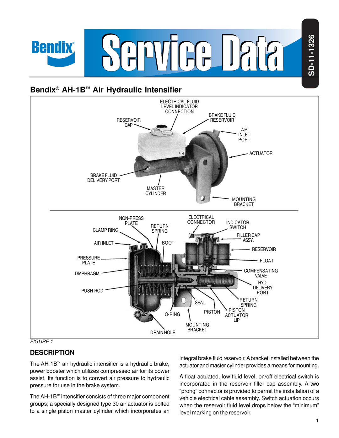
FIGURE 1 |
|
|
|
| |
DESCRIPTION
The
The
integral brake fluid reservoir. A bracket installed between the actuator and master cylinder provides a means for mounting.
A float actuated, low fluid level, on/off electrical switch is incorporated in the reservoir filler cap assembly. A two “prong” connector is provided to permit the installation of a vehicle electrical cable assembly. Switch actuation occurs when the reservoir fluid level drops below the “minimum” level marking on the reservoir.
1