BENDIX SD-11-1326 manual Master Cylinder Assembly, Bench Bleeding

Models: SD-11-1326

1 8
Download 8 pages 5.25 Kb
Page 8
Image 8
Master Cylinder Assembly

2.Place the push rod and diaphragm assembly into the pressure plate and place non-pressure plate onto the push rod. Check to assure that the spring is in proper position (each end contained and centered in the spring guides).

3.Orient the pressure and non-pressure plates as marked and compress the spring by pushing down on the non-pressure plate. Retain with a clamp or light pressure from a press. Be sure the ferrule on the pressure plate is properly oriented and the edges of the non-pressure plate, diaphragm, and pressure plate are equally distributed around the entire circumference.

4.Install clamping ring and retain with the two bolts and nuts. Torque to 130-150 inch pounds. IMPORTANT: Be sure the beads of the pressure plate and the non-pressure plate are contained by the clamping ring a full 360°. Tap around the circumference of the clamp ring to assure it is seated evenly all around.

5.Install a new gasket on the mounting studs of the nonpressure plate of the assembled actuator and put the assembly aside.

Master Cylinder Assembly

6.Install new o-rings on the master cylinder mounting flange and the master cylinder piston.

7.Carefully insert the spring and piston into the master cylinder body. Making certain not to damage the seal and o-ring. The lip seal and o-ring must enter the body last. Depress and hold the piston by inserting a dull object into the recess in the end of the piston. Piston actuator lip should be completely past the compensating TRT valve assembly port to allow for proper installation of the compensating valve assembly. Install the compensating valve assembly into the threaded port of the top of the master cylinder. Be sure compensating valve is installed between the two larger diameters on the piston. Torque to 30-40 foot pounds. NOTE: The compensating valve assembly should retain the piston assembly in the master cylinder if installed correctly. (See Figure 10.)

8.Install a new seal on the bottom of the reservoir and place both on the master cylinder. Be sure reservoir is oriented so that holes for the Phillips screws line up with the holes on the master cylinder. Install the two Phillips screws and lockwashers and tighten snugly.

9.Install the reservoir retaining nut onto the compensating valve through the reservoir cover opening. Use a 1-1/4" socket and torque to 13-16 foot pounds.

10.Install the reservoir filler cap assembly on the reservoir.

11.Clamp the mounting bracket securely in a vise, making sure it is oriented so that the unit may be assembled, and lining up the marks made prior to disassembly.
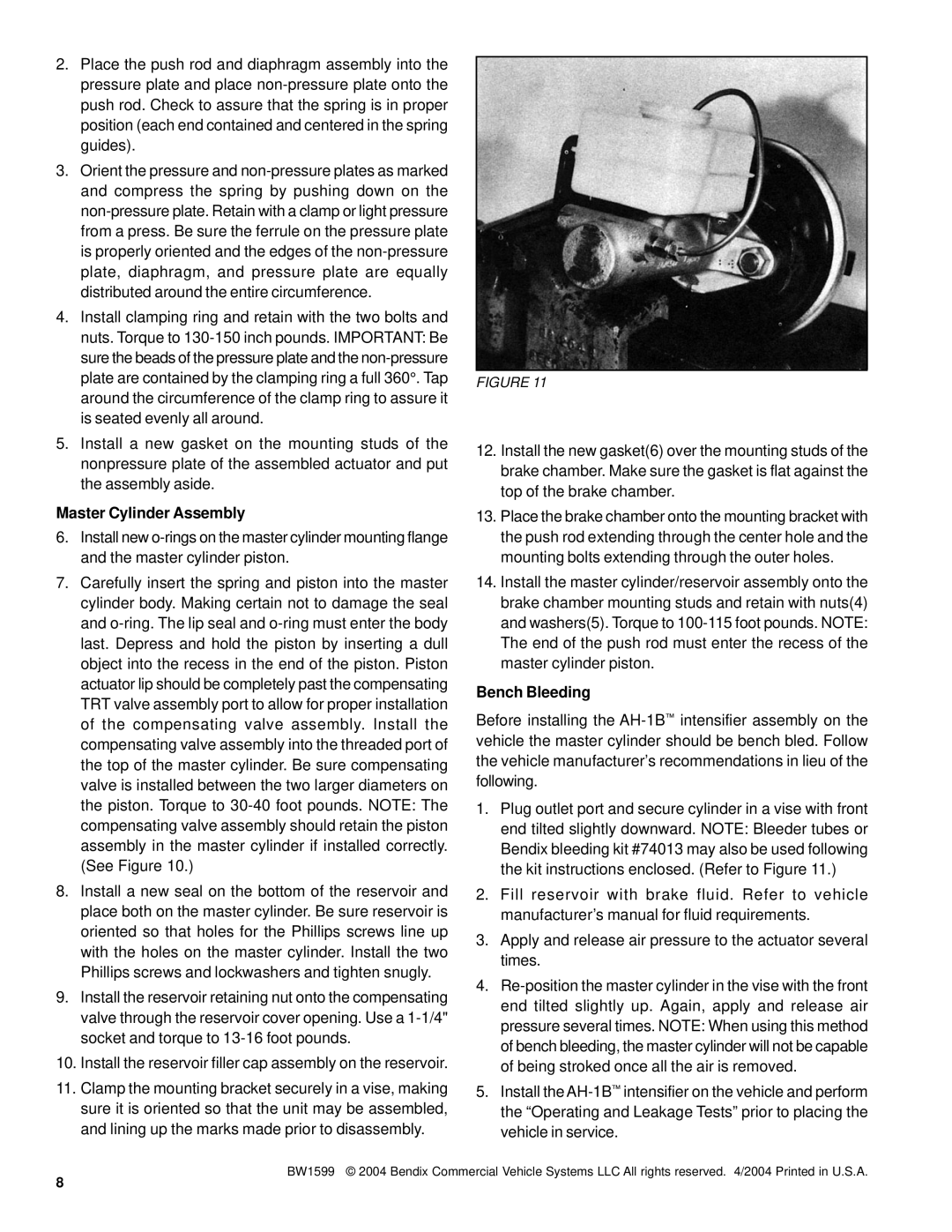
FIGURE 11

12.Install the new gasket(6) over the mounting studs of the brake chamber. Make sure the gasket is flat against the top of the brake chamber.

13.Place the brake chamber onto the mounting bracket with the push rod extending through the center hole and the mounting bolts extending through the outer holes.

14.Install the master cylinder/reservoir assembly onto the brake chamber mounting studs and retain with nuts(4) and washers(5). Torque to 100-115 foot pounds. NOTE: The end of the push rod must enter the recess of the master cylinder piston.

Bench Bleeding

Before installing the AH-1Bintensifier assembly on the vehicle the master cylinder should be bench bled. Follow the vehicle manufacturer’s recommendations in lieu of the following.

1.Plug outlet port and secure cylinder in a vise with front end tilted slightly downward. NOTE: Bleeder tubes or Bendix bleeding kit #74013 may also be used following the kit instructions enclosed. (Refer to Figure 11.)

2.Fill reservoir with brake fluid. Refer to vehicle manufacturer’s manual for fluid requirements.

3.Apply and release air pressure to the actuator several times.

4.Re-position the master cylinder in the vise with the front end tilted slightly up. Again, apply and release air pressure several times. NOTE: When using this method of bench bleeding, the master cylinder will not be capable of being stroked once all the air is removed.

5.Install the AH-1Bintensifier on the vehicle and perform the “Operating and Leakage Tests” prior to placing the vehicle in service.

BW1599 © 2004 Bendix Commercial Vehicle Systems LLC All rights reserved. 4/2004 Printed in U.S.A.

8

Page 8
Image 8
BENDIX SD-11-1326 manual Master Cylinder Assembly, Bench Bleeding