5.Note and mark the orientation of the actuator and master cylinder to the mounting bracket. Remove the two nuts and washers from the mounting studs of the actuator (use a 15/16" socket wrench). Separate the master cylinder and actuator from the mounting bracket and retain the actuator for later disassembly. CAUTION: Piston under spring load and retained by the push rod only when compensating tilt valve assembly has been removed. (Refer to Figure 8.)
6.Remove the
7.Remove the piston assembly and spring from the body of the master cylinder. (Refer to Figure 9.)
Actuator Disassembly
8.Mark the relationship of the clamp ring, pressure and
9.Remove the spring seat, spring, and boot from the push rod and separate the diaphragm from the push rod. (NOTE: Do not separate the diaphragm from the push rod.) If the diaphragm is to be replaced, a new push rod and diaphragm assembly will be required.
CLEANING & INSPECTION
1.Wash all master cylinder parts retained during disassembly in clean DOT 3 or 4 brake fluid. CAUTION: DO NOT use any solvent other than clean brake fluid for cleaning or flushing master cylinder parts. The use of unapproved solvents with a trace of mineral oil will damage rubber parts.
2.Remove all sediment or foreign material from the bottom of the fluid reservoir. If the reservoir is equipped with filters, make certain they are thoroughly cleaned. If the filters are thoroughly plugged and/or cannot be cleaned, the entire brake system should be flushed. If the filter cannot be cleaned, it may be removed after the system is flushed.
3.Inspect the condition of the piston. Measure the major diameter (around the top edge of the
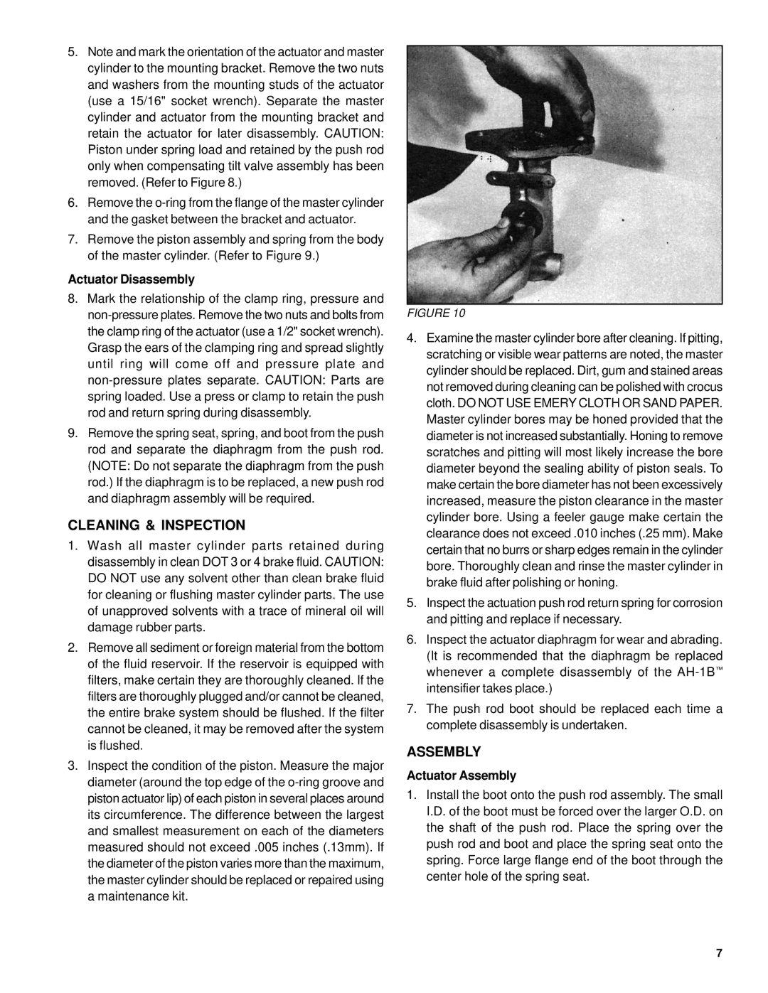
FIGURE 10
4.Examine the master cylinder bore after cleaning. If pitting, scratching or visible wear patterns are noted, the master cylinder should be replaced. Dirt, gum and stained areas not removed during cleaning can be polished with crocus cloth. DO NOT USE EMERY CLOTH OR SAND PAPER. Master cylinder bores may be honed provided that the diameter is not increased substantially. Honing to remove scratches and pitting will most likely increase the bore diameter beyond the sealing ability of piston seals. To make certain the bore diameter has not been excessively increased, measure the piston clearance in the master cylinder bore. Using a feeler gauge make certain the clearance does not exceed .010 inches (.25 mm). Make certain that no burrs or sharp edges remain in the cylinder bore. Thoroughly clean and rinse the master cylinder in brake fluid after polishing or honing.
5.Inspect the actuation push rod return spring for corrosion and pitting and replace if necessary.
6.Inspect the actuator diaphragm for wear and abrading. (It is recommended that the diaphragm be replaced whenever a complete disassembly of the
7.The push rod boot should be replaced each time a complete disassembly is undertaken.
ASSEMBLY
Actuator Assembly
1.Install the boot onto the push rod assembly. The small I.D. of the boot must be forced over the larger O.D. on the shaft of the push rod. Place the spring over the push rod and boot and place the spring seat onto the spring. Force large flange end of the boot through the center hole of the spring seat.
7