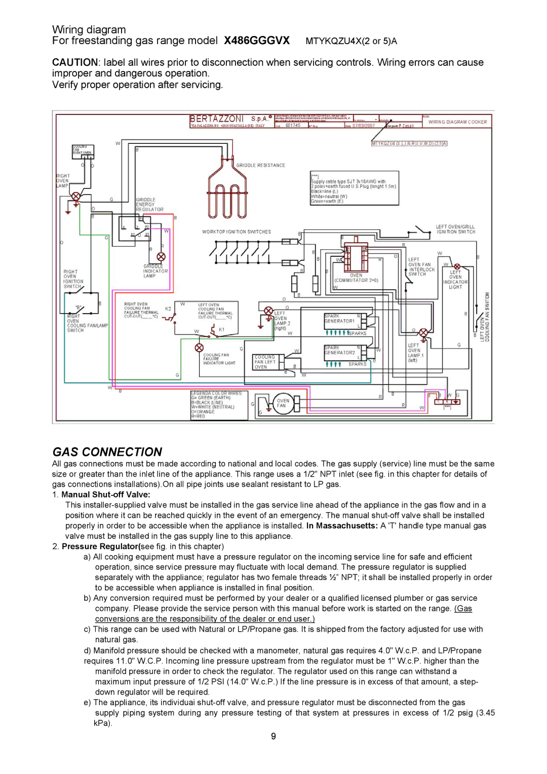
Wiring diagram
For freestanding gas range model X486GGGVX MTYKQZU4X(2 or 5)A
CAUTION: label all wires prior to disconnection when servicing controls. Wiring errors can cause improper and dangerous operation.
Verify proper operation after servicing.
GAS CONNECTION
All gas connections must be made according to national and local codes. The gas supply (service) line must be the same size or greater than the inlet line of the appliance. This range uses a 1/2" NPT inlet (see fig. in this chapter for details of gas connections installations).On all pipe joints use sealant resistant to LP gas.
1.Manual Shut-off Valve:
This
2.Pressure Regulator(see fig. in this chapter)
a)All cooking equipment must have a pressure regulator on the incoming service line for safe and efficient operation, since service pressure may fluctuate with local demand. The pressure regulator is supplied separately with the appliance; regulator has two female threads ½” NPT; it shall be installed properly in order to be accessible when appliance is installed in final position.
b)Any conversion required must be performed by your dealer or a qualified licensed plumber or gas service company. Please provide the service person with this manual before work is started on the range. (Gas conversions are the responsibility of the dealer or end user.)
c)This range can be used with Natural or LP/Propane gas. It is shipped from the factory adjusted for use with natural gas.
d)Manifold pressure should be checked with a manometer, natural gas requires 4.0" W.c.P. and LP/Propane requires 11.0" W.C.P. Incoming line pressure upstream from the regulator must be 1" W.c.P. higher than the
manifold pressure in order to check the regulator. The regulator used on this range can withstand a maximum input pressure of 1/2 PSI (14.0" W.c.P.) If the line pressure is in excess of that amount, a step- down regulator will be required.
e)The appliance, its individuai
supply piping system during any pressure testing of that system at pressures in excess of 1/2 psig (3.45 kPa).
9