8. INSTALL BLOWER HOUSING
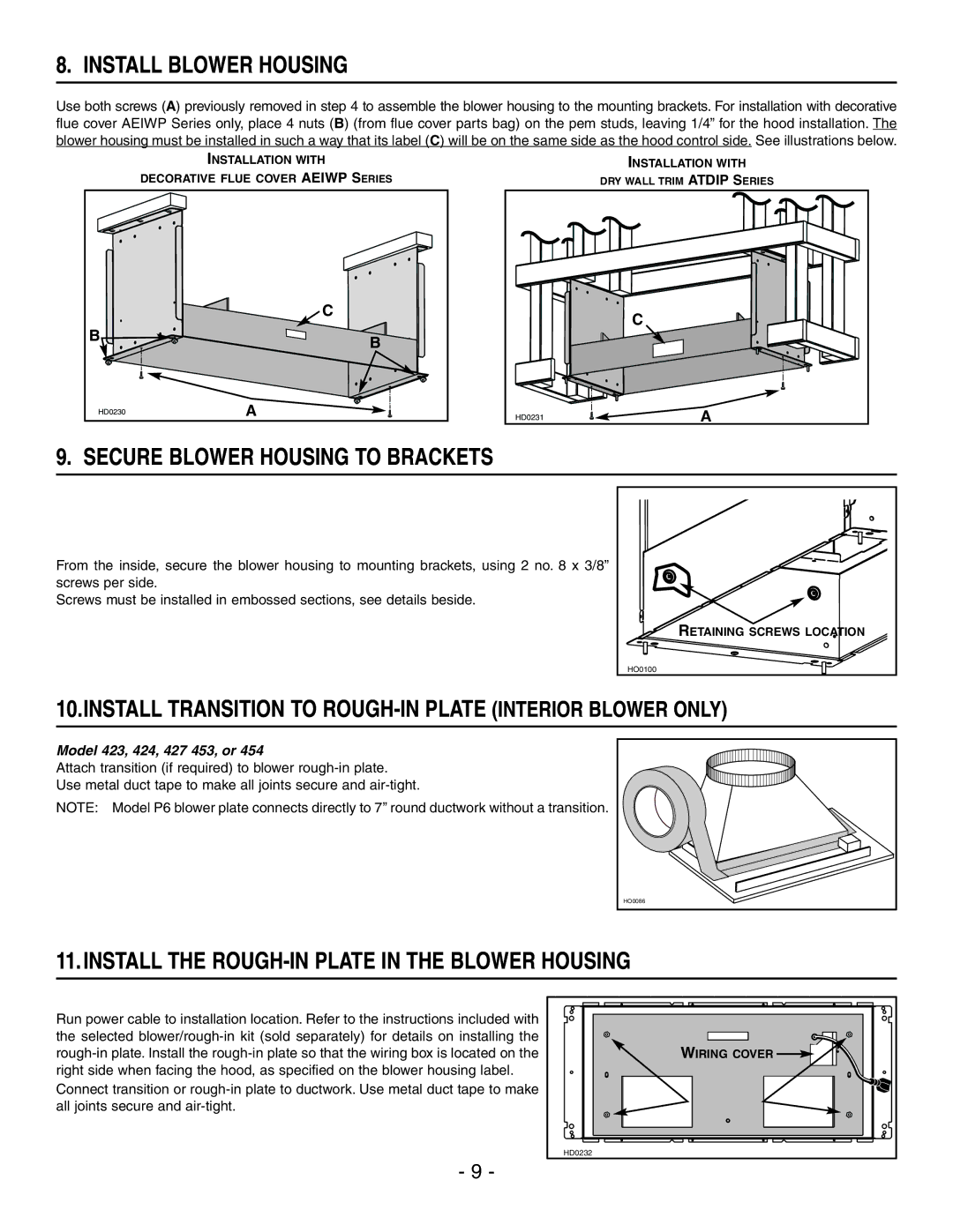
Use both screws (A) previously removed in step 4 to assemble the blower housing to the mounting brackets. For installation with decorative flue cover AEIWP Series only, place 4 nuts (B) (from flue cover parts bag) on the pem studs, leaving 1/4” for the hood installation. The blower housing must be installed in such a way that its label (C) will be on the same side as the hood control side. See illustrations below.
INSTALLATION WITH
DECORATIVE FLUE COVER AEIWP SERIES
| C |
B | B |
| |
HD0230 | A |
INSTALLATION WITH
DRY WALL TRIM ATDIP SERIES
| C |
HD0231 | A |
9. SECURE BLOWER HOUSING TO BRACKETS
From the inside, secure the blower housing to mounting brackets, using 2 no. 8 x 3/8” screws per side.
Screws must be installed in embossed sections, see details beside.
RETAINING SCREWS LOCATION |
HO0100 |
10.INSTALL TRANSITION TO ROUGH-IN PLATE (INTERIOR BLOWER ONLY)
Model 423, 424, 427 453, or 454
Attach transition (if required) to blower
Use metal duct tape to make all joints secure and
NOTE: Model P6 blower plate connects directly to 7’’ round ductwork without a transition.
HO0086 |
11.INSTALL THE ROUGH-IN PLATE IN THE BLOWER HOUSING
Run power cable to installation location. Refer to the instructions included with the selected
Connect transition or
WIRING COVER |
HD0232 |
- 9 -