10 | 11 | 12 |
ADDITIONAL IMPORTANT SAFETY INSTRUCTIONS
•![]() WARNING: When using electric tools, basic safety precautions should always be followed to reduce risk of fire, electric shock, and personal injury, including the following:
WARNING: When using electric tools, basic safety precautions should always be followed to reduce risk of fire, electric shock, and personal injury, including the following:
•Do not incinerate the battery even if it is severely damaged or is completely worn out. The battery can explode in a fire. Check with local codes for possible special disposal instructions.
•If any leakage of liquid from the battery cells occurs, discontinue use immediately and return the battery to your local Black & Decker Service Center or authorized service facility.
•Never attempt to open the battery for any reason. If the plastic housing of the battery breaks or cracks, immediately discontinue use and do not recharge.
•Do not charge appliance in rain or in wet locations.
•Use only the following type and size battery: Black & Decker 244373 - 12V.
•Use only Black and Decker 12V charger 244374.
•Exercise care in handling batteries in order not to short the battery with conducting materials such as rings, bracelets and keys. The battery or conductor may overheat and cause burns.
•Do not open or mutilate the battery. Released electrolyte is corrosive and may cause damage to the eyes or skin. It may be toxic if swallowed.
•If the battery case cracks due to a fall or other impact and the electrolyte gel leaks out, wipe it up with a cloth, neutralize the acid with any alkaline substance such as ammonia solution or baking soda. If the electrolyte gets on your skin, immediately flush with water and consult a doctor.
•Do not use battery for anything other than with this product or other designated Black & Decker product.
ASSEMBLY INSTRUCTIONS
Before assembling your Cordless String Trimmer, check that you have received the following in the shipping carton.
See Figure 1.
A.Trimmer/Edger.
B.Guard.
C.Charger and Charger Bracket.
D.Hardware Bag with (2) screws and (2) plastic anchors.
![]() WARNING: The guard must always be on the tool to protect the user. Use of the unit without the guard will overheat the motor, and void the warranty.
WARNING: The guard must always be on the tool to protect the user. Use of the unit without the guard will overheat the motor, and void the warranty.
NEVER OPERATE TOOL WITHOUT GUARD FIRMLY IN PLACE.
1.Position the open center of the guard over the line feed head (Figure 2).
2.Hinge the guard on the hook located on the lower motor housing. Ensure the line is free, and not tucked under the guard. Once hooked, lightly pull on the back edge of the guard and push the guard down until the 2 latches snap into place on the motor housing.
(Figure 2)
3.Using a phillips screwdriver, screw the preassembled screw in the guard, into the motor housing. (Figure 3)
BATTERY
THE LEAD ACID BATTERY FOR YOUR TRIMMER IS ONLY PARTIALLY CHARGED AT THE FACTORY. BEFORE USING YOUR TRIMMER, THE BATTERY MUST BE CHARGED FOR A MINIMUM OF 24 HOURS.
•Your trimmer is equipped with a charger bracket that may be mounted firmly to a wall in your garage, shed or similar building. (Hardware for hanging the bracket is included in the plastic bag packed with the trimmer.) Charging your battery in this bracket is very convenient because it hangs the tool up, out of the way and ensures a good, solid contact between the charging terminals.
MOUNTING THE CHARGER BRACKET (FIGURE 4)
1.If you intend to mount the charger bracket on a wall, follow the instructions listed below.
2.Use the hardware provided (Figure 1D) only if hanging on conventional hollow wall construction such as drywall over studs. If not, use the appropriate fasteners for the particular wall material.
3.Use the charger bracket to mark the locations of the holes required. Be sure to mount the bracket high enough so that the trimmer can hang freely from it; about 4 feet (1.2m) from the floor and close enough to an electrical outlet to
4.a) Conventional hollow wall: Drill a .250 in. (6mm) diameter hole at each marked location. Insert the plastic anchors supplied into the holes and insert one of the screws into each anchor.
b)Alternative wall materials: Insert fasteners as appropriate making sure screw heads are small enough to fit through bracket.
5.Tighten the screws until the heads are above the wall just enough so that the charger bracket will fit between the wall and the screw head.
6.Place the charger bracket on the wall (hook end up) and make sure that the power cord is positioned in the side slot. Press the charger bracket over the screw heads and slide it down until it sits firmly on the screws.
7.Firmly tighten both screws.
LED INDICATOR LIGHT
The unit is equipped with a red LED charging indicator light, located on the upper left side of the unit (Figure 1). The indicator light will come on when the unit is properly connected to the charging base and the power plug is inserted into the electrical outlet. The light will remain on, so long as the unit is properly connected to the powered charging base. It is recommended to store the unit on the charger during the growing season, with the charger plugged in, to have the battery charged for the next use.
TO CHARGE YOUR BATTERY, FOLLOW THE STEPS BELOW
1.Install the trimmer onto the charger bracket by positioning the handle cavity, shown in Figure 4 over the hook of the charger bracket.
2.Rotate the trimmer down, keeping the hook engaged with the handle cavity, and position the charge port over the bracket’s charge pin (Figure 4).
3.Plug the charger into any standard 120 volt, 60Hz outlet. Charging will be automatically controlled until you remove the trimmer from the bracket.
4.It is recommended that the trimmer be left on charge, during the growing season. For winter or other extended periods of storage, it is recommended that the unit be fully charged prior to storage.
OPERATION INSTRUCTIONS
![]() CAUTION: ALWAYS WEAR EYE PROTECTION.
CAUTION: ALWAYS WEAR EYE PROTECTION.
![]() CAUTION: Inspect area to be trimmed and remove any wire, cord, or
CAUTION: Inspect area to be trimmed and remove any wire, cord, or
OPERATE THE TRIMMER/EDGER
•To turn trimmer on, pull the lock out button, shown in Figure 1, backwards and, then squeeze the trigger switch. To turn the tool off, release the trigger.
•Slowly swing trimmer
•To convert for maintenance edging, turn off the tool. (See Figure 6) Holding the trimmer with
one hand by the auxiliary handle, grasp the trimmer head collar and push in direction of arrow and rotate the trimmer head clockwise (when viewed from the switch end) until it stops, (half turn), release your hand. The tool is locked in the edger position.
Rotate the wire edge guide forward and down into place before edging, as shown in Figure 7.
•To operate as a maintenance edger, position trimmer above sidewalk as shown in Figure 8.
•Return to trimming position by turning the tool off, push in direction of arrow and rotating the trimmer head counter clockwise until it stops. When using the tool in the trimmer mode you may choose to fold the wire edge guide up out of the way.
CUTTING LINE
LINE FEEDING
Your trimmer uses .065 in. (1.65 mm) diameter, ROUND nylon line to cut grass and weeds quickly and easily. During use, the tip of the nylon line will become frayed and worn and the special self feeding line hub will automatically feed and trim a fresh length of line. Cutting line will wear faster and require more feeding if the cutting or edging is done along sidewalks or other abrasive surfaces or heavier weeds are being cut. The advanced automatic line feeding mechanism senses when more cutting line is needed and feeds and trims the correct length of line whenever its required. DO NOT BUMP unit on ground in attempt to feed line or for any other purposes.
CLEARING JAMS AND TANGLED LINES
From time to time, especially when cutting thick or stalky weeds, the line feeding hub may become clogged with sap or other material and the line will become jammed as a result. To clear the jam, follow the steps listed below.
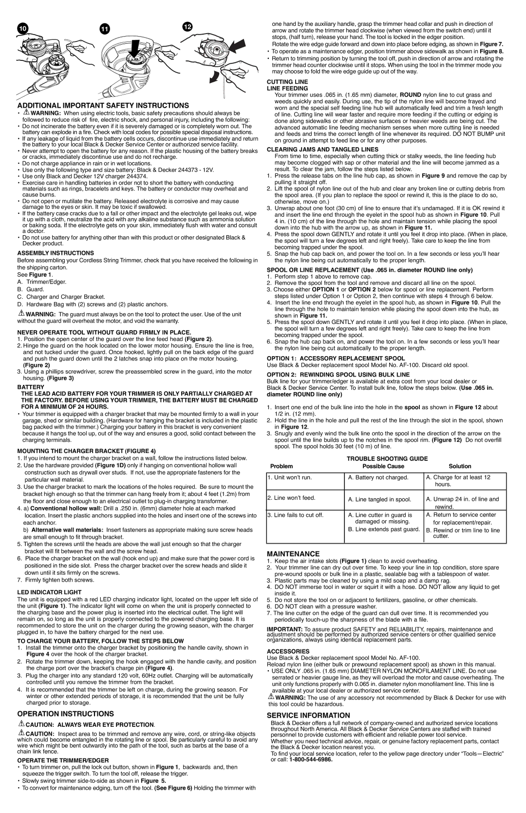
1.Press the release tabs on the line hub cap, as shown in Figure 9 and remove the cap by pulling it straight off.
2.Lift the spool of nylon line out of the hub and clear any broken line or cutting debris from the spool area. (If you plan to replace the spool or rewind it, this is the place to do so, otherwise, move on.)
3.Unwrap about one foot (30 cm) of line to ensure that it’s undamaged. If it is OK rewind it and insert the line end through the eyelet in the spool hub as shown in Figure 10. Pull 4 in. (10 cm) of the line through the hole and maintain tension while placing the spool down into the hub with the arrow up, as shown in Figure 11.
4.Press the spool down GENTLY and rotate it until you feel it drop into place. (When in place, the spool will turn a few degrees left and right freely). Take care to keep the line from becoming trapped under the spool.
5.Snap the hub cap back on, and power the tool on. In a few seconds or less you’ll hear the nylon line being cut automatically to the proper length.
SPOOL OR LINE REPLACEMENT (Use .065 in. diameter ROUND line only)
1.Perform step 1 above to remove cap.
2.Remove the spool from the tool and remove and discard all line on the spool.
3.Choose either OPTION 1 or OPTION 2 below for spool or line replacement. Perform steps listed under Option 1 or Option 2, then continue with steps 4 through 6 below.
4.Insert the line end through the eyelet in the spool hub, as shown in Figure 10. Pull the line through the hole to maintain tension while placing the spool down into the hub, as shown in Figure 11.
5.Press the spool down GENTLY and rotate it until you feel it drop into place. (When in place, the spool will turn a few degrees left and right freely). Take care to keep the line from becoming trapped under the spool.
6.Snap the hub cap back on, and power the tool on. In a few seconds or less you’ll hear the nylon line being cut automatically to the proper length.
OPTION 1: ACCESSORY REPLACEMENT SPOOL
Use Black & Decker replacement spool Model No.
OPTION 2: REWINDING SPOOL USING BULK LINE
Bulk line for your trimmer/edger is available at extra cost from your local dealer or Black & Decker Service Center. To install bulk line, follow the steps below. (Use .065 in. diameter ROUND line only)
1.Insert one end of the bulk line into the hole in the spool as shown in Figure 12 about 1/2 in. (12 mm).
2.Hold the line in the hole and pull the rest of the line through the slot in the spool, shown in Figure 12.
3.Snugly and evenly wind the bulk line onto the spool in the direction of the arrow on the spool until the line builds up to the notches in the spool rim. (Figure 12) Do not overfill spool. The spool holds 30 feet (10 m) of line.
|
| TROUBLE SHOOTING GUIDE | |
Problem | Possible Cause | Solution | |
|
|
|
|
1. | Unit won’t run. | A. Battery not charged. | A. Charge for at least 12 |
|
|
| hours. |
|
|
|
|
2. | Line won’t feed. | A. Line tangled in spool. | A. Unwrap 24 in. of line and |
|
|
| rewind. |
3. | Line fails to cut off. | A. Line cutter in guard is | A. Return to service center |
|
| damaged or missing. | for replacement/repair. |
|
| B. Line extends past guard. | B. Rewind or trim line to line |
|
|
| cutter. |
|
|
|
|
|
|
|
|
MAINTENANCE
1.Keep the air intake slots (Figure 1) clean to avoid overheating.
2.Your trimmer line can dry out over time. To keep your line in top condition, store spare
3.Plastic parts may be cleaned by using a mild soap and a damp rag.
4.DO NOT immerse tool in water or squirt it with a hose. DO NOT allow any liquid to get inside it.
5.Do not store the tool on or adjacent to fertilizers, gasoline, or other chemicals.
6.DO NOT clean with a pressure washer.
7.The line cutter on the edge of the guard can dull over time. It is recommended you periodically
IMPORTANT: To assure product SAFETY and RELIABILITY, repairs, maintenance and adjustment should be performed by authorized service centers or other qualified service organizations, always using identical replacement parts.
ACCESSORIES
Use Black & Decker replacement spool Model No.
Reload nylon line (either bulk or prewound replacement spool) as shown in this manual.
•USE ONLY .065 in. (1.65 mm) DIAMETER NYLON MONOFILAMENT LINE. Do not use serrated or heavier gauge line, as they will overload the motor and cause overheating. The unit only functions properly with 0.065 in. diameter nylon monofilament line. This line is available at your local dealer or authorized service center.
![]() WARNING: The use of any accessory not recommended by Black & Decker for use with this tool could be hazardous.
WARNING: The use of any accessory not recommended by Black & Decker for use with this tool could be hazardous.
SERVICE INFORMATION
Black & Decker offers a full network of
Whether you need technical advice, repair, or genuine factory replacement parts, contact the Black & Decker location nearest you.
To find your local service location, refer to the yellow page directory under