FIG. 1 | 1 |
2
![]() 3
3
6
5
7
4
8 ![]()
23
22
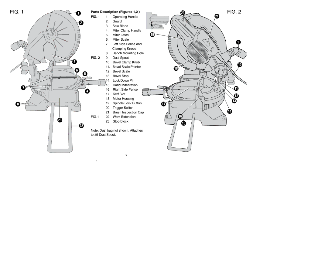
Parts Description (Figures 1,2 ) | 20 | FIG. 2 | |
FIG. 1 | 1. Operating Handle |
| 21 |
2.Guard
3. Saw Blade
4.Miter Clamp Handle
5. Miter Latch | 19 |
6.Miter Scale
| 7. | Left Side Fence and | 9 |
|
| ||
|
| Clamping Knobs |
|
| 8. | Bench Mounting Hole |
|
FIG. 2 | 9. | Dust Spout |
|
| 10. | Bevel Clamp Knob | 10 |
| 11. | Bevel Scale Pointer | |
| 18 | ||
| 12. | Bevel Scale | |
|
| ||
| 13. | Bevel Stop |
|
| 14. | Lock Down Pin |
|
| 15. | Hand Indentation | 11 |
| 16. | Right Side Fence | |
| 17. | Kerf Slot | 12 |
| 18. | Motor Housing | |
| 13 | ||
| 19. | Spindle Lock Button | |
| 17 | ||
| 20. | Trigger Switch | 14 |
| 21. | Brush Inspection Cap | |
FIG.1 | 22. | Work Extension | 16 |
| 23. | Stop Block | 15 |
|
|
|
Note: Dust bag not shown. Attaches to #9 Dust Spout.
2