Operation
![]() WARNING: Before attempting any of the following operations, make sure that the tool is switched off and unplugged and that the saw blade has stopped. Used saw blades can be hot.
WARNING: Before attempting any of the following operations, make sure that the tool is switched off and unplugged and that the saw blade has stopped. Used saw blades can be hot.
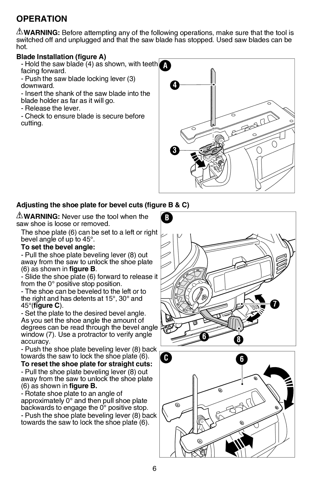
Blade Installation (figure A)
- Hold the saw blade (4) as shown, with teeth facing forward.
- Push the saw blade locking lever (3) downward.
- Insert the shank of the saw blade into the blade holder as far as it will go.
- Release the lever.
- Check to ensure blade is secure before cutting.
A |
4 |
3 |
Adjusting the shoe plate for bevel cuts (figure B & C)
![]() WARNING: Never use the tool when the saw shoe is loose or removed.
WARNING: Never use the tool when the saw shoe is loose or removed.
The shoe plate (6) can be set to a left or right bevel angle of up to 45°.
To set the bevel angle:
- Pull the shoe plate beveling lever (8) out away from the saw to unlock the shoe plate
(6) as shown in figure B.
- Slide the shoe plate (6) forward to release it from the 0° positive stop position.
- The shoe can be beveled to the left or to the right and has detents at 15°, 30° and 45°(figure C).
- Set the plate to the desired bevel angle. As you set the shoe angle the amount of degrees can be read through the bevel angle window (7). Use a protractor to verify angle accuracy.
- Push the shoe plate beveling lever (8) back towards the saw to lock the shoe plate (6).
To reset the shoe plate for straight cuts: - Pull the shoe plate beveling lever (8) out away from the saw to unlock the shoe plate
(6) as shown in figure B.
- Rotate shoe plate to an angle of approximately 0° and then pull shoe plate backwards to engage the 0° positive stop.
- Push the shoe plate beveling lever (8) back towards the saw to lock the shoe plate (6).
B |
|
|
|
| 7 |
| 6 | 8 |
|
| |
C |
| 6 |
6