Installation and Connection Instructions | 4 |
|
|
AA
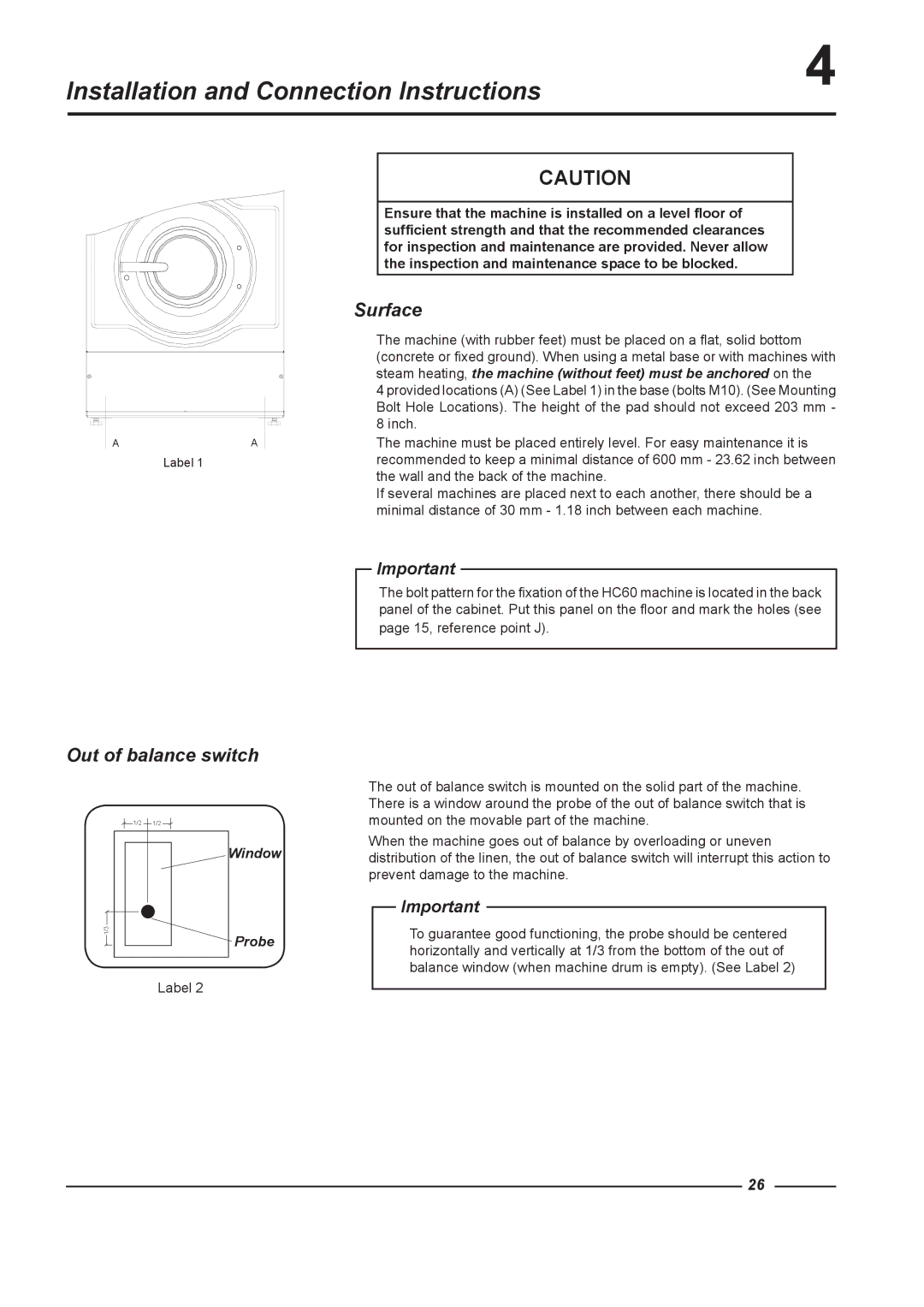
Label 1
CAUTION
Ensure that the machine is installed on a level floor of sufficient strength and that the recommended clearances for inspection and maintenance are provided. Never allow the inspection and maintenance space to be blocked.
Surface
The machine (with rubber feet) must be placed on a flat, solid bottom (concrete or fixed ground). When using a metal base or with machines with steam heating, the machine (without feet) must be anchored on the
4 provided locations (A) (See Label 1) in the base (bolts M10). (See Mounting Bolt Hole Locations). The height of the pad should not exceed 203 mm - 8 inch.
The machine must be placed entirely level. For easy maintenance it is recommended to keep a minimal distance of 600 mm - 23.62 inch between the wall and the back of the machine.
If several machines are placed next to each another, there should be a minimal distance of 30 mm - 1.18 inch between each machine.
Important
The bolt pattern for the fixation of the HC60 machine is located in the back panel of the cabinet. Put this panel on the floor and mark the holes (see
page 15, reference point J).
Out of balance switch
1/2 | 1/2 |
| Window |
1/3 | Probe |
| |
| Label 2 |
The out of balance switch is mounted on the solid part of the machine. There is a window around the probe of the out of balance switch that is mounted on the movable part of the machine.
When the machine goes out of balance by overloading or uneven distribution of the linen, the out of balance switch will interrupt this action to prevent damage to the machine.
Important
To guarantee good functioning, the probe should be centered horizontally and vertically at 1/3 from the bottom of the out of balance window (when machine drum is empty). (See Label 2)
26