Chapter 2: Overview
5 | 6 | 7 | 8 |
|
| ||||||||
|
|
|
|
|
|
|
|
|
|
|
|
|
|
|
|
|
|
|
|
|
|
|
|
|
|
|
|
|
|
|
|
|
|
|
|
|
|
|
|
|
|
|
|
|
|
|
|
|
|
|
|
|
|
|
|
|
|
|
|
|
|
|
|
|
|
|
|
|
|
|
|
|
|
|
|
|
|
|
|
|
|
|
|
|
|
|
|
|
|
|
|
|
|
|
|
|
|
|
|
|
|
|
|
|
|
|
|
|
|
|
|
| 9 | 10 |
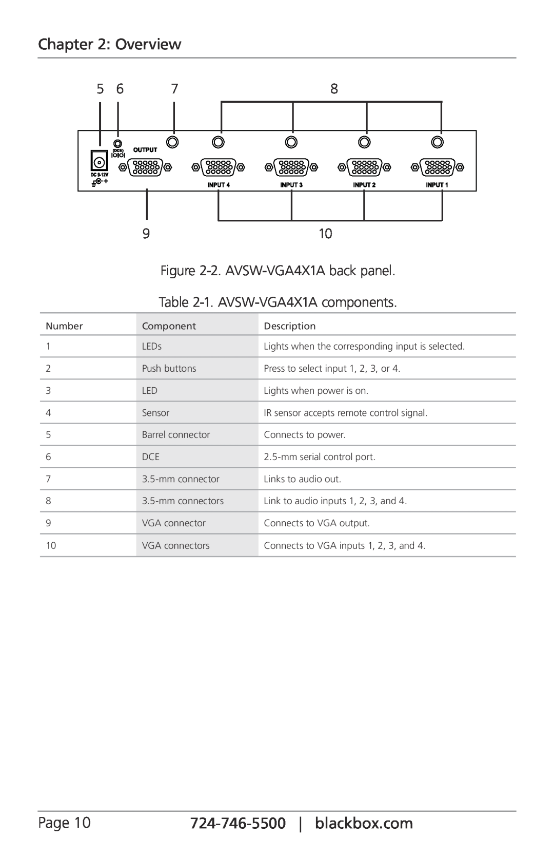
| Figure | |
| Table | |
|
|
|
Number | Component | Description |
|
|
|
1 | LEDs | Lights when the corresponding input is selected. |
|
|
|
2 | Push buttons | Press to select input 1, 2, 3, or 4. |
|
|
|
3 | LED | Lights when power is on. |
|
|
|
4 | Sensor | IR sensor accepts remote control signal. |
|
|
|
5 | Barrel connector | Connects to power. |
|
|
|
6 | DCE | |
|
|
|
7 | Links to audio out. | |
|
|
|
8 | Link to audio inputs 1, 2, 3, and 4. | |
|
|
|
9 | VGA connector | Connects to VGA output. |
|
|
|
10 | VGA connectors | Connects to VGA inputs 1, 2, 3, and 4. |
|
|
|
Page 10 |