MD885C-R2, MD885A-R3, MD885AE-R2, 34336 specifications
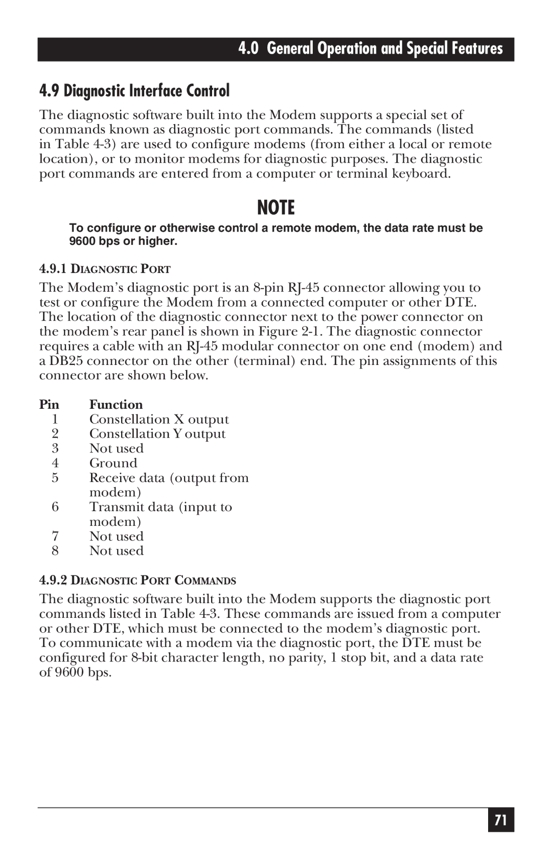
Black Box 34336 is a versatile and powerful solution designed to meet the diverse needs of data communication and management in various environments. This device integrates advanced technologies that enhance connectivity, streaming capacity, and security, making it ideal for both corporate and personal use.One of the primary features of the Black Box 34336 is its robust connectivity options. It supports multiple protocols, allowing seamless integration with different network systems, including Ethernet, Wi-Fi, and other wired options. This versatility ensures that users can rely on the device in various settings, from small offices to larger enterprise environments. With the ability to manage both wired and wireless connections, it provides the flexibility needed to create a comprehensive network infrastructure.
Another significant characteristic of the Black Box 34336 is its cutting-edge data encryption capabilities. Security is paramount in today's digital landscape, and this device employs advanced encryption techniques that protect sensitive information during transmission. Whether facilitating remote work or supporting in-house operations, the device ensures that data remains secure, reducing the risk of unauthorized access and breaches.
The device also features an intuitive user interface, making it easy to configure and manage settings. Users can quickly access different functionalities, including monitoring network performance, adjusting security protocols, and managing connected devices. The user-friendly design caters to both seasoned IT professionals and those less tech-savvy, promoting broader usability across organizational levels.
Performance is another critical area where the Black Box 34336 excels. It boasts high-speed data transfer rates, enabling efficient data handling for various applications. Whether it is video streaming, large file transfers, or real-time data analytics, users can expect minimal latency and reliable performance. This capability is particularly beneficial for businesses that require real-time data processing and communication.
In summary, the Black Box 34336 stands out as a reliable and feature-rich solution for anyone looking to enhance their networking capabilities. With its versatile connectivity options, robust security features, user-friendly interface, and high-performance data handling, it addresses a myriad of needs in the modern digital age. As technology continues to evolve, the Black Box 34336 proves to be a forward-thinking solution designed to adapt and thrive in an ever-changing landscape. Whether for personal use or within an organizational framework, this device offers a comprehensive approach to data communication and management.

