Chapter 4: Installation
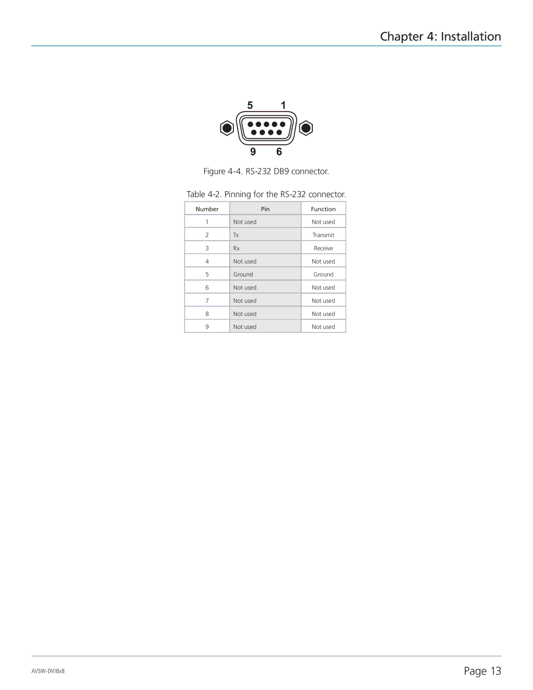
Figure 4-4. RS-232 DB9 connector.
Table 4-2. Pinning for the RS-232 connector.
Number |
| Pin | Function |
|
|
|
|
1 | Not used |
| Not used |
|
|
|
|
2 | Tx |
| Transmit |
|
|
|
|
3 | Rx |
| Receive |
|
|
|
|
4 | Not used |
| Not used |
|
|
|
|
5 | Ground |
| Ground |
|
|
|
|
6 | Not used |
| Not used |
|
|
|
|
7 | Not used |
| Not used |
|
|
|
|
8 | Not used |
| Not used |
|
|
|
|
9 | Not used |
| Not used |
|
|
|
|
Page 13 |
