OPERATION (continued) |
| ||
|
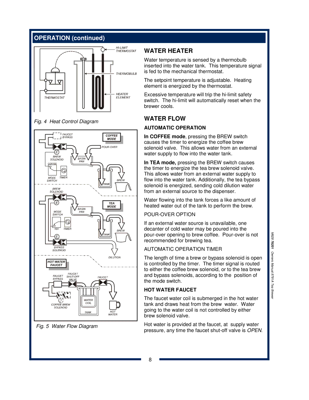
| WATER HEATER | |
|
| Water temperature is sensed by a thermobulb | |
|
| inserted into the water tank. This temperature signal | |
|
| is fed to the mechanical thermostat. | |
|
| The setpoint temperature is adjustable. Heating | |
|
| element is energized by the thermostat. | |
|
| Excessive temperature will trip the | |
|
| switch. The | |
|
| brewer cools. | |
Fig. 4 | Heat Control Diagram | WATER FLOW | |
AUTOMATIC OPERATION | |||
|
| ||
|
| In COFFEE mode, pressing the BREW switch | |
|
| causes the timer to energize the coffee brew | |
|
| solenoid valve. This allows water from an external | |
|
| water supply to flow into the water tank. | |
|
| In TEA mode, pressing the BREW switch causes | |
|
| the timer to energize the tea brew solenoid valve. | |
|
| This allows water from an external water supply to | |
|
| flow into the water tank. Additionally, the tea bypass | |
|
| solenoid is energized, sending cold dilution water | |
|
| from an external source to the dispenser. | |
|
| Water flowing into the tank forces a like amount of | |
|
| heated water out of the tank to perform the brew. | |
|
|
| |
|
| If an external water source is unavailable, one | |
|
| decanter of cold water may be poured into the | |
|
| ||
|
| recommended for brewing tea. | |
|
| AUTOMATIC OPERATION TIMER | |
|
| The length of time a brew or bypass solenoid is open | |
|
| is controlled by the timer. The timer signal is routed | |
|
| to either the coffee brew solenoid, or to the tea brew | |
|
| and bypass solenoids, according to the position of | |
|
| the mode switch. | |
|
| HOT WATER FAUCET | |
|
| The faucet water coil is submerged in the hot water | |
|
| tank and draws heat from the brew water. Water | |
|
| going to the water coil is not controlled by either | |
|
| brew solenoid valve. | |
Fig. 5 Water Flow Diagram | Hot water is provided at the faucet, at supply water | ||
pressure, any time the faucet | |||
|
| ||
|
| 8 | |
M628 76201 Owners Manual 8781A Tea Brewer