1 | 4 | 6 | 7 |
|
|
|
| 8 |
|
|
|
|
|
|
|
|
|
|
|
18VCT |
|
|
|
|
|
|
|
|
|
|
|
|
|
|
|
|
|
|
|
AC | AUX OUT | MAIN | AUX IN | Trim | 8 | Trim | 7 | Trim | 6 | Trim | 5 | Trim | 4 | Trim | 3 | Trim | 2 | Trim | 1 |
Ground |
|
|
|
|
|
|
|
| |||||||||||
| On |
|
|
|
|
|
|
|
|
|
|
|
|
|
|
|
|
|
|
| Off |
| G - + Line |
| Line G - + | Line |
| Line G - + | Line G - + | Line G - + | Line G - + | Line G - + | |||||||
Power | G - + | G - + | G - + | ||||||||||||||||
Phantom | 0dB |
| Mic |
| Mic |
| Mic |
| Mic |
| Mic |
| Mic |
| Mic |
| Mic |
| |
2 | 3 | 5 |
|
|
|
|
| 9 | 10 |
|
|
|
|
|
|
|
|
|
|
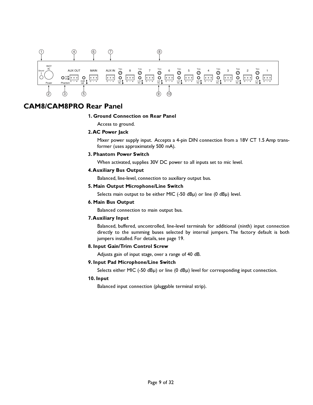
CAM8/CAM8PRO Rear Panel
1. Ground Connection on Rear Panel
Access to ground.
2.AC Power Jack
Mixer power supply input. Accepts a
3. Phantom Power Switch
When activated, supplies 30V DC power to all inputs set to mic level.
4.Auxiliary Bus Output
Balanced,
5. Main Output Microphone/Line Switch
Selects main output to be either MIC
6. Main Bus Output
Balanced connection to main output bus.
7.Auxiliary Input
Balanced, buffered, uncontrolled,
8. Input Gain/Trim Control Screw
Adjusts gain of input stage, over a range of 40 dB.
9. Input Pad Microphone/Line Switch
Selects either MIC
10. Input
Balanced input connection (pluggable terminal strip).
Page 9 of 32