PBX Ground Start Trunk Port
In this configuration, the unit supplies 24V talk battery, a contact in the Tip circuit, and loop current detector in the ring line. When the ground start trunk grounds Ring, the unit responds by closing the connection to Tip, which completes the access procedure.When the loop is opened, the page ends.The unit follows the status of the trunk.
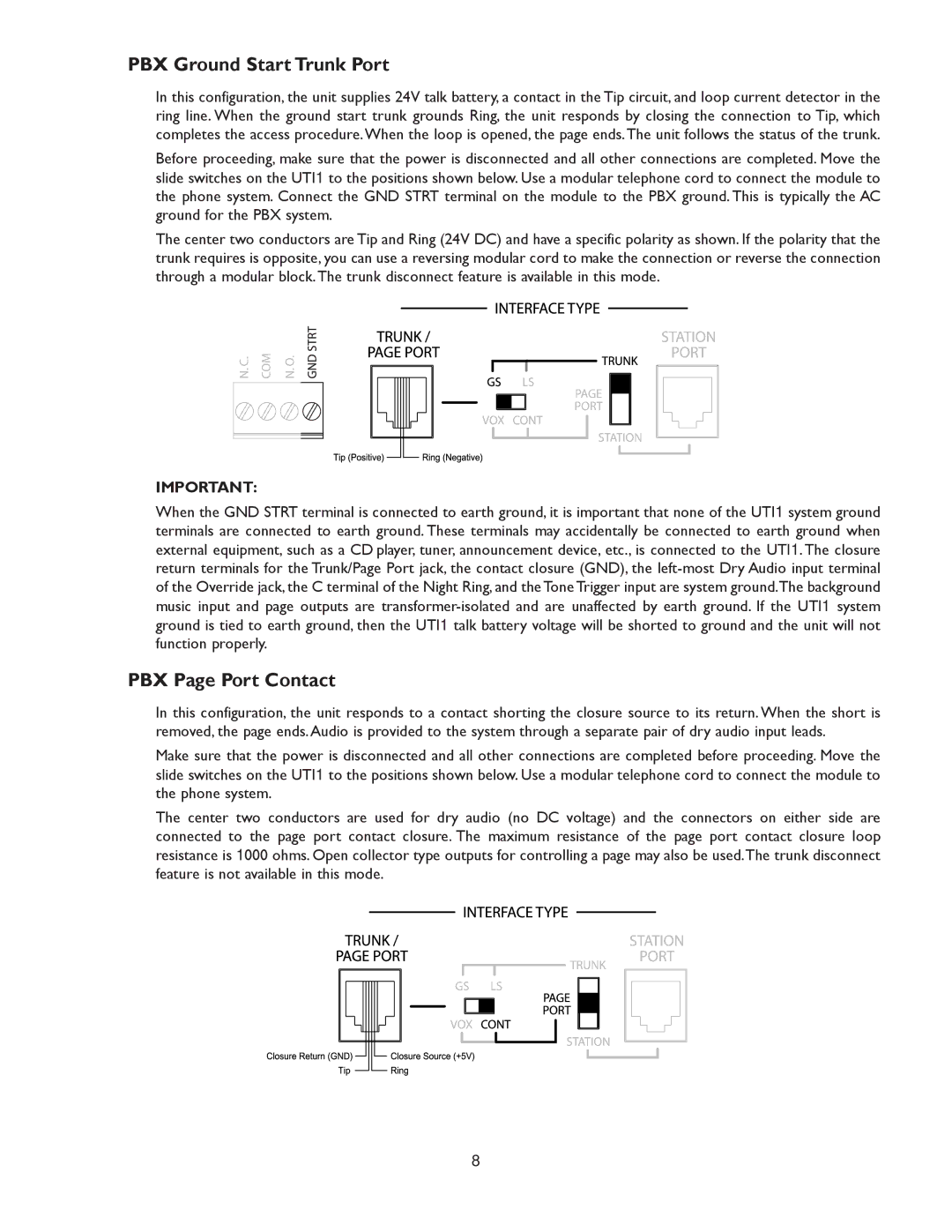
Before proceeding, make sure that the power is disconnected and all other connections are completed. Move the slide switches on the UTI1 to the positions shown below. Use a modular telephone cord to connect the module to the phone system. Connect the GND STRT terminal on the module to the PBX ground. This is typically the AC ground for the PBX system.
The center two conductors are Tip and Ring (24V DC) and have a specific polarity as shown. If the polarity that the trunk requires is opposite, you can use a reversing modular cord to make the connection or reverse the connection through a modular block.The trunk disconnect feature is available in this mode.
IMPORTANT:
When the GND STRT terminal is connected to earth ground, it is important that none of the UTI1 system ground terminals are connected to earth ground. These terminals may accidentally be connected to earth ground when external equipment, such as a CD player, tuner, announcement device, etc., is connected to the UTI1. The closure return terminals for the Trunk/Page Port jack, the contact closure (GND), the
PBX Page Port Contact
In this configuration, the unit responds to a contact shorting the closure source to its return. When the short is removed, the page ends. Audio is provided to the system through a separate pair of dry audio input leads.
Make sure that the power is disconnected and all other connections are completed before proceeding. Move the slide switches on the UTI1 to the positions shown below. Use a modular telephone cord to connect the module to the phone system.
The center two conductors are used for dry audio (no DC voltage) and the connectors on either side are connected to the page port contact closure. The maximum resistance of the page port contact closure loop resistance is 1000 ohms. Open collector type outputs for controlling a page may also be used.The trunk disconnect feature is not available in this mode.
8