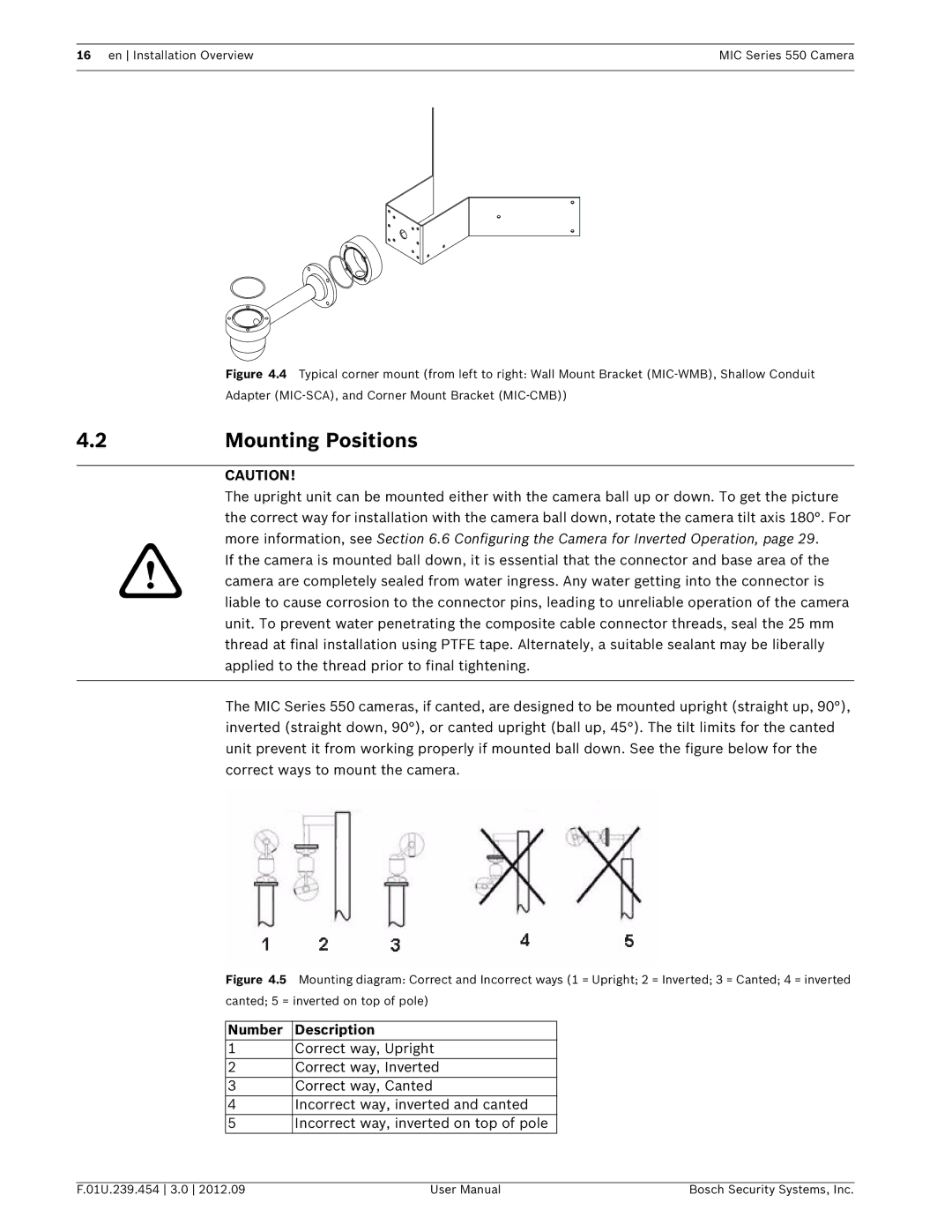
550 specifications
Bosch Appliances has long been recognized for its commitment to quality and innovative solutions, and the Bosch Appliances 550 series exemplifies this reputation. The 550 series combines sleek design with advanced technology to enhance the user's kitchen experience.One of the standout features of the Bosch 550 series is its remarkable efficiency. Designed with energy-saving technologies, these appliances boast an impressive Energy Star rating, significantly reducing power consumption without compromising performance. This not only leads to substantial savings on utility bills but also contributes to a more sustainable lifestyle.
The 550 series includes various appliances such as refrigerators, dishwashers, ovens, and cooktops, each meticulously designed to fit seamlessly into any kitchen design. The appliances are equipped with a minimalist aesthetic, featuring clean lines and a modern finish that complements both traditional and contemporary interiors.
In terms of cooking performance, the Bosch 550 ovens incorporate advanced convection technology. This ensures even baking results by circulating hot air throughout the oven. Additionally, the True European Convection for even baking results makes these ovens ideal for baking enthusiasts. Furthermore, the ovens come with a self-cleaning feature, saving homeowners time and effort in maintaining their appliance.
Dishwashers in the 550 series feature Bosch’s renowned Quiet Design technology, ensuring minimal noise during operation. This is particularly beneficial for open-concept living spaces where noise can be disruptive. With a range of wash cycles and options, including a rinse-only cycle and a sanitize cycle, these dishwashers are designed to cater to various cleaning needs.
Smart technology is another prominent characteristic of the Bosch 550 appliances. Many models in the series come with Wi-Fi connectivity, allowing users to control their appliances remotely through a smartphone app. This feature enhances convenience, enabling users to monitor cooking progress or receive maintenance alerts.
The Bosch Appliances 550 series also prioritizes user-friendly controls. Intuitive touch controls and digital displays streamline the process of selecting functions, resulting in a smoother experience in the kitchen.
In summary, Bosch Appliances 550 series is a perfect blend of efficiency, advanced technology, and sleek design. With features like energy efficiency, smart connectivity, and user-friendly controls, this series represents Bosch’s dedication to elevating the modern kitchen experience while maintaining brand integrity and quality.