Wiring to the unitin Canada
WARNING
The unit must be installed by a qualified electrician, in accordance with the current version of the Canadian Electrical Code. The unit must be grounded.
IMPORTANT
•When the PowerStar is not within sight of the electrical circuit brea kers, a circuit breaker lockout or additional local means of disconnection for all
•As per the Canadian Electrical Code,
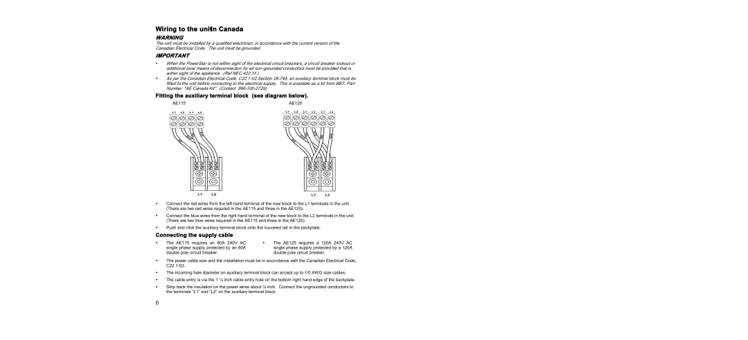
Fitting the auxiliary terminal block (see diagram below).
AE115 | AE125 |
•Connect the red wires from the left hand terminal of the new block to the L1 terminals in the unit. (There are two red wires required in the AE115 and three in the AE125).
•Connect the blue wires from the right hand terminal of the new block to the L2 terminals in the unit. (There are two blue wires required in the AE115 and three in the AE125).
•Push and click the auxiliary terminal block onto the louvered rail in the backplate.
Connecting the supply cable
• | The AE115 requires an 80A 240V AC | • | The AE125 requires a 120A 240V AC |
| single phase supply protected by an 80A |
| single phase supply protected by a 120A |
| double pole circuit breaker. |
| double pole circuit breaker. |
•The power cable size and the installation must be in accordance with the Canadian Electrical Code,
•The incoming hole diameter on auxiliary terminal block can accept up to 1/0 AWG size cables.
•The cable entry is via the 1 ¼ inch cable entry hole on the bottom right hand edge of the backplate.
•Strip back the insulation on the power wires about ½ inch. Connect the ungrounded conductors to the terminals “L1” and “L2” on the auxiliary terminal block.
6
