IMPORTANT
When the PowerStar is not within sight of the electrical circuit breakers, a circuit breaker lockout or additional local means of disconnection for all
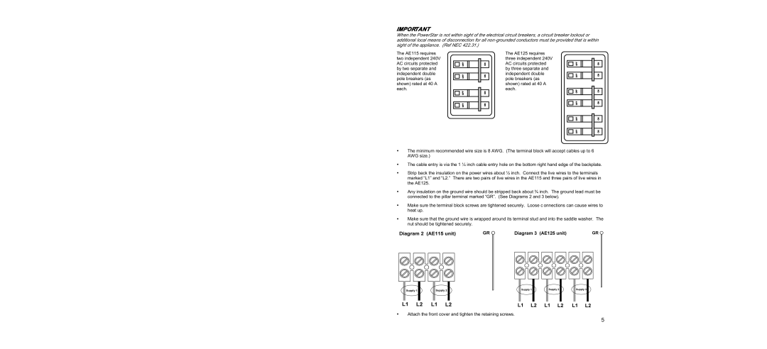
The AE115 requires two independent 240V AC circuits protected by two separate and independent double pole breakers (as shown) rated at 40 A each.
OFF OFFOFF OFF
ON ONON ON
The AE125 requires three independent 240V AC circuits protected by three separate and independent double pole breakers (as shown) rated at 40 A each.
OFF OFFOFF OFF
ON ONON ON
OFF | ON |
OFF | ON |
•The minimum recommended wire size is 8 AWG. (The terminal block will accept cables up to 6 AWG size.)
•The cable entry is via the 1 ¼ inch cable entry hole on the bottom right hand edge of the backplate.
•Strip back the insulation on the power wires about ½ inch. Connect the live wires to the terminals marked “L1” and “L2.” There are two pairs of live wires in the AE115 and three pairs of live wires in the AE125.
•Any insulation on the ground wire should be stripped back about ¾ inch. The ground lead must be connected to the pillar terminal marked “GR”. (See Diagrams 2 and 3 below).
•Make sure the terminal block screws are tightened securely. Loose c onnections can cause wires to heat up.
•Make sure that the ground wire is wrapped around its terminal stud and into the saddle washer. The nut should be tightened securely.
•Attach the front cover and tighten the retaining screws.
5
