Installation Instructions
CLEARANCES FOR FLUE TERMINAL (front of heater)
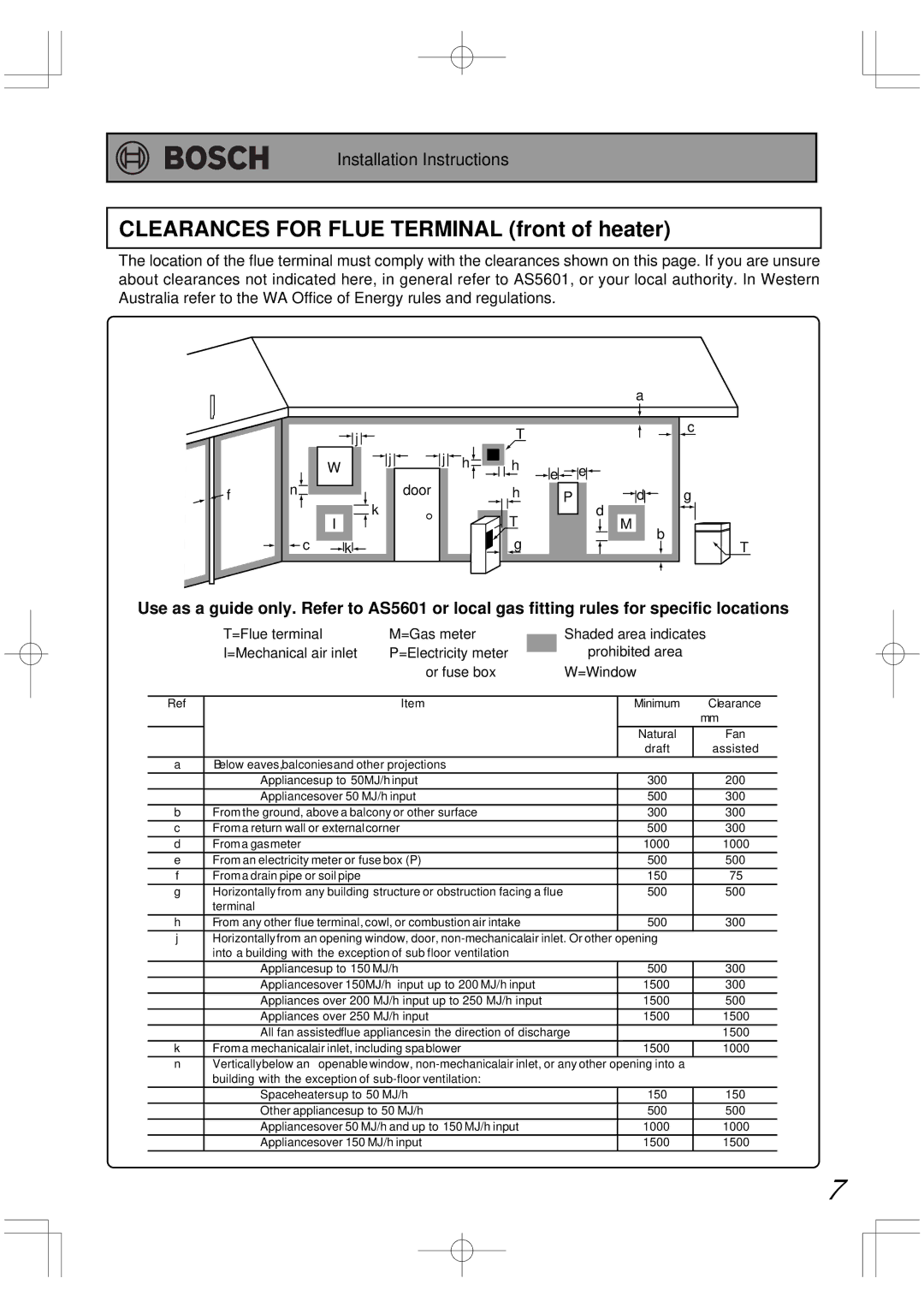
The location of the flue terminal must comply with the clearances shown on this page. If you are unsure about clearances not indicated here, in general refer to AS5601, or your local authority. In Western Australia refer to the WA Office of Energy rules and regulations.
![]() f
f
|
|
|
|
|
|
|
|
|
|
|
|
|
|
|
|
|
|
|
|
|
|
|
|
|
|
|
|
|
|
|
|
|
|
|
|
|
|
|
|
|
|
|
|
| a |
|
|
|
|
|
|
|
|
|
| |||
|
|
|
|
|
|
|
|
|
|
|
|
|
|
|
|
|
|
|
|
|
|
|
|
|
|
|
|
|
|
|
|
|
|
|
|
|
|
|
|
|
|
|
|
|
|
|
|
|
|
|
|
|
|
|
|
|
|
|
|
|
|
|
|
|
|
|
|
|
|
|
|
|
|
|
|
|
|
|
|
|
|
|
|
|
|
|
|
|
|
|
|
|
|
|
|
|
|
|
|
|
|
|
|
|
|
|
|
|
|
|
|
|
|
|
|
|
|
|
|
|
|
|
|
| j |
|
|
|
|
|
|
|
|
|
|
|
|
|
|
|
|
|
|
| T |
|
|
|
|
|
|
|
|
|
|
|
|
|
|
|
|
|
|
|
|
|
| c | ||||||||
|
|
|
|
|
|
|
|
|
|
|
|
|
|
|
|
|
|
|
|
|
|
|
|
|
|
|
|
|
|
|
|
|
|
|
|
|
|
|
|
|
|
|
|
|
|
|
|
|
|
|
| |||||||
|
|
|
|
|
|
|
|
|
|
|
|
|
|
|
|
|
|
|
|
|
|
|
|
|
|
|
|
|
|
|
|
|
|
|
|
|
|
|
|
|
|
|
|
|
|
|
|
|
|
|
| |||||||
|
|
|
|
|
|
|
|
|
|
|
|
|
|
|
|
|
|
|
|
|
|
|
|
|
|
|
|
|
|
|
|
|
|
|
|
|
|
|
|
|
|
|
|
|
|
|
|
|
|
|
|
|
|
|
| |||
|
|
|
| W |
|
|
|
|
|
| j |
|
|
|
|
| j |
|
| h |
|
|
|
| h | e |
|
|
| e |
|
|
|
|
|
|
|
|
|
|
|
|
|
|
|
|
|
|
|
|
| |||||||
|
|
|
|
|
|
|
|
|
|
|
|
|
|
|
|
|
|
|
|
|
|
|
|
|
|
|
|
|
|
|
|
|
|
|
|
|
|
|
|
|
|
|
|
| ||||||||||||||
|
|
|
|
|
|
|
|
|
|
|
|
|
|
|
|
|
|
|
|
|
|
|
|
|
|
|
|
|
|
|
|
|
|
|
|
|
|
|
|
|
| |||||||||||||||||
n |
|
|
|
|
|
|
|
|
|
|
|
|
|
|
|
|
|
|
|
|
|
|
|
|
|
|
|
|
|
|
|
|
|
|
|
|
| � |
|
|
|
|
|
|
|
|
|
| ||||||||||
|
|
|
|
|
|
|
|
|
|
|
|
| door |
|
|
|
| h |
|
|
|
|
|
|
|
|
|
|
|
|
|
|
|
|
| |||||||||||||||||||||||
|
|
|
|
|
|
|
|
| k |
|
|
|
|
|
|
| P |
|
|
|
|
|
|
|
|
| d |
|
|
|
|
|
|
| g | |||||||||||||||||||||||
|
|
|
|
|
|
|
|
|
|
|
|
|
|
|
|
|
|
|
|
|
|
|
| T |
|
|
|
|
|
| d |
|
|
|
|
|
|
|
|
|
|
|
|
|
| |||||||||||||
|
|
|
|
|
|
|
|
|
|
|
|
|
|
|
|
|
|
|
|
|
|
|
|
|
|
|
|
|
|
|
|
|
|
|
|
|
|
| ||||||||||||||||||||
|
|
|
|
| I |
|
|
|
|
|
|
|
|
|
|
|
|
|
|
|
|
|
|
|
|
|
|
|
|
|
|
|
|
|
| M |
| b | ||||||||||||||||||||
|
| c |
|
|
|
|
|
|
|
|
|
|
|
|
|
|
|
|
|
|
|
|
|
|
|
| g |
|
|
|
|
|
|
|
|
|
|
|
|
|
|
|
|
|
|
|
| |||||||||||
|
|
|
| k |
|
|
|
|
|
|
|
|
|
|
|
|
|
|
|
|
|
|
|
|
|
|
|
|
|
|
|
|
|
|
|
|
|
|
|
|
|
|
|
|
|
|
|
|
| T | ||||||||
|
|
|
|
|
|
|
|
|
|
|
|
|
|
|
|
|
|
|
|
|
|
|
|
|
|
|
|
|
|
|
|
|
|
|
|
|
|
|
|
|
|
|
|
|
|
|
|
|
|
|
|
|
|
|
|
|
|
|
Use as a guide only. Refer to AS5601 or local gas fitting rules for specific locations
| T=Flue terminal | M=Gas meter |
|
| Shaded area indicates | ||
|
| ||||||
| I=Mechanical air inlet | P=Electricity meter |
|
| prohibited area |
| |
|
|
| |||||
|
| or fuse box | W=Window |
| |||
|
|
|
|
|
| ||
Ref |
| Item |
| Minimum | Clearance | ||
|
|
|
|
|
|
| mm |
|
|
|
|
|
| Natural | Fan |
|
|
|
|
|
| draft | assisted |
a | Below eaves,balconiesand other projections |
|
|
| |||
| Appliancesup to 50MJ/h input |
| 300 | 200 | |||
| Appliancesover 50 MJ/h input |
| 500 | 300 | |||
b | From the ground, above a balcony or other surface |
| 300 | 300 | |||
c | From a return wall or external corner |
| 500 | 300 | |||
d | From a gasmeter |
|
|
|
| 1000 | 1000 |
e | From an electricity meter or fuse box (P) |
| 500 | 500 | |||
f | From a drain pipe or soil pipe |
|
|
|
| 150 | 75 |
g | Horizontally from any building structure or obstruction facing a flue |
| 500 | 500 | |||
| terminal |
|
|
|
|
|
|
h | From any other flue terminal, cowl, or combustion air intake |
| 500 | 300 | |||
jHorizontallyfrom an opening window, door,
| Appliancesup to 150 MJ/h | 500 | 300 |
| Appliancesover 150MJ/h input up to 200 MJ/h input | 1500 | 300 |
| Appliances over 200 MJ/h input up to 250 MJ/h input | 1500 | 500 |
| Appliances over 250 MJ/h input | 1500 | 1500 |
| All fan assistedflue appliancesin the direction of discharge |
| 1500 |
k | From a mechanicalair inlet, including spablower | 1500 | 1000 |
n | Verticallybelow an openablewindow, | opening into a |
|
| building with the exception of |
|
|
| Spaceheatersup to 50 MJ/h | 150 | 150 |
| Other appliancesup to 50 MJ/h | 500 | 500 |
| Appliancesover 50 MJ/h and up to 150 MJ/h input | 1000 | 1000 |
| Appliancesover 150 MJ/h input | 1500 | 1500 |
7