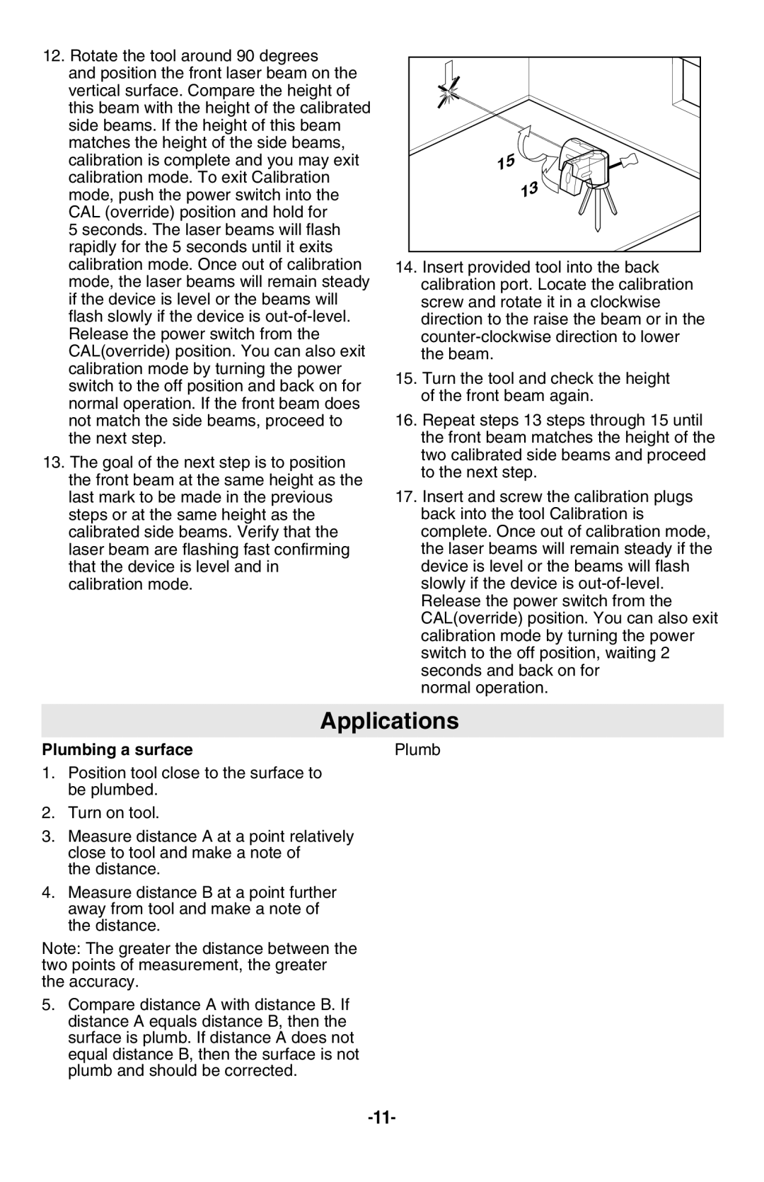
12.Rotate the tool around 90 degrees
and position the front laser beam on the vertical surface. Compare the height of this beam with the height of the calibrated side beams. If the height of this beam matches the height of the side beams, calibration is complete and you may exit calibration mode. To exit Calibration mode, push the power switch into the CAL (override) position and hold for
5 seconds. The laser beams will flash rapidly for the 5 seconds until it exits calibration mode. Once out of calibration mode, the laser beams will remain steady if the device is level or the beams will flash slowly if the device is
13.The goal of the next step is to position the front beam at the same height as the last mark to be made in the previous steps or at the same height as the calibrated side beams. Verify that the laser beam are flashing fast confirming that the device is level and in calibration mode.
15 |
13 |
14.Insert provided tool into the back calibration port. Locate the calibration screw and rotate it in a clockwise direction to the raise the beam or in the
15.Turn the tool and check the height of the front beam again.
16.Repeat steps 13 steps through 15 until the front beam matches the height of the two calibrated side beams and proceed to the next step.
17.Insert and screw the calibration plugs back into the tool Calibration is complete. Once out of calibration mode, the laser beams will remain steady if the device is level or the beams will flash slowly if the device is
normal operation.
Applications
Plumbing a surface
1.Position tool close to the surface to be plumbed.
2.Turn on tool.
3.Measure distance A at a point relatively close to tool and make a note of
the distance.
4.Measure distance B at a point further away from tool and make a note of the distance.
Note: The greater the distance between the two points of measurement, the greater the accuracy.
5.Compare distance A with distance B. If distance A equals distance B, then the surface is plumb. If distance A does not equal distance B, then the surface is not plumb and should be corrected.
Plumb |
B |
A |
