4.0 Hardware Installation
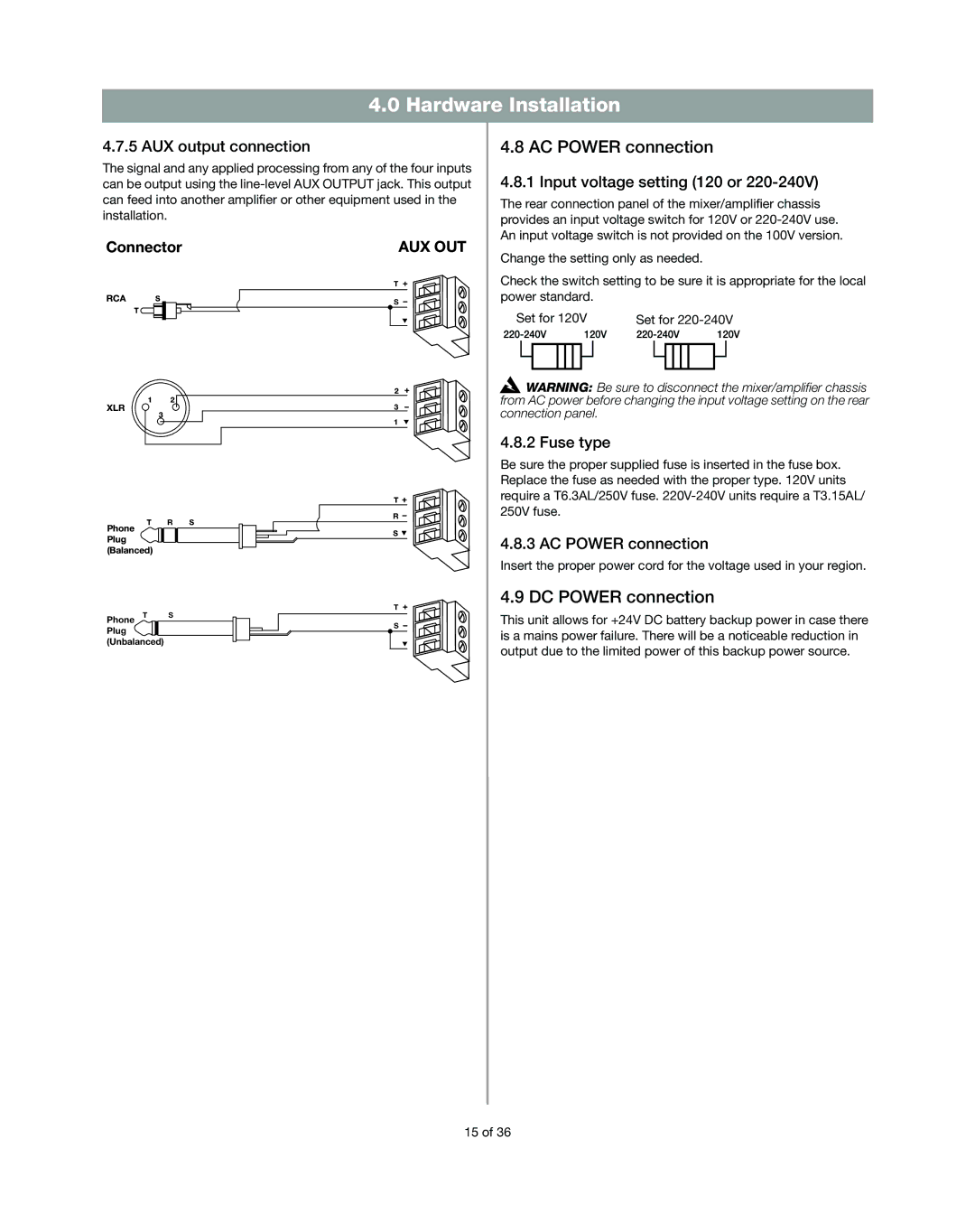
4.7.5 AUX output connection
The signal and any applied processing from any of the four inputs can be output using the
4.8 AC POWER connection
4.8.1 Input voltage setting (120 or 220-240V)
The rear connection panel of the mixer/amplifier chassis provides an input voltage switch for 120V or
Connector
RCA S
T
1 2
XLR
3
T R S
Phone
Plug (Balanced)
Phone T S Plug (Unbalanced)
AUX OUT
T ![]()
S
2
3
1
T ![]()
R
S ![]()
T ![]()
S
Change the setting only as needed.
Check the switch setting to be sure it is appropriate for the local power standard.
Set for 120V | Set for | ||||||||||
|
|
|
|
|
|
|
|
|
|
|
|
|
|
|
|
|
|
|
|
|
|
|
|
![]() WARNING: Be sure to disconnect the mixer/amplifier chassis from AC power before changing the input voltage setting on the rear connection panel.
WARNING: Be sure to disconnect the mixer/amplifier chassis from AC power before changing the input voltage setting on the rear connection panel.
4.8.2 Fuse type
Be sure the proper supplied fuse is inserted in the fuse box. Replace the fuse as needed with the proper type. 120V units require a T6.3AL/250V fuse.
4.8.3 AC POWER connection
Insert the proper power cord for the voltage used in your region.
4.9 DC POWER connection
This unit allows for +24V DC battery backup power in case there is a mains power failure. There will be a noticeable reduction in output due to the limited power of this backup power source.
15 of 36