SERVICE PROCEDURE RG-VI
Burner Operation Inspection, Adjustment
Cleaning and Replacement
MAIN BURNER: Inspection, Adjustment,
Cleaning and Replacement
At periodic intervals (not more then 6 months) a visual inspection should be made of the main burner for proper operation and to insure no debris accumulating.
Main burner should light smoothly from pilot and burn with a blue flame with a minimum of yellow tips.
Steel burner models have a self adjusting air mixture and do not have an adjustable air shutter. Cast iron burner can have the gas and air mixture properly proportioned by adjusting the air shutter on the mixer face of the main burner (see step 2 below).
Main burner must be free from any debris accumulation that may effect burner operation (see burner cleaning procedure on page 17).
CAST IRON BURNER ADJUSTMENT
![]()
![]()
![]() DANGER
DANGER
Under no circumstances shall flammable materials be used or stored in the vicinity of the water heater. With the inner door removed the Bradford White Defender Safety System will be inactivated. If flammable vapors are present, a fire or explosion may result causing property damage, personal injury or death.
Upon completion of the cast iron burner adjustment procedure, the inner door must be replaced per SERVICE PROCEDURE
![]()
![]()
![]() WARNING
WARNING
Inner door and burner components may be HOT when performing this operation. Take
necessary precaution to prevent personal injury.
Step 1. With main burner in operation, remove right side inner door per service procedure I, steps 3b & 3c. Be sure to maintain wire connection to resettable thermal switch for this adjustment procedure.
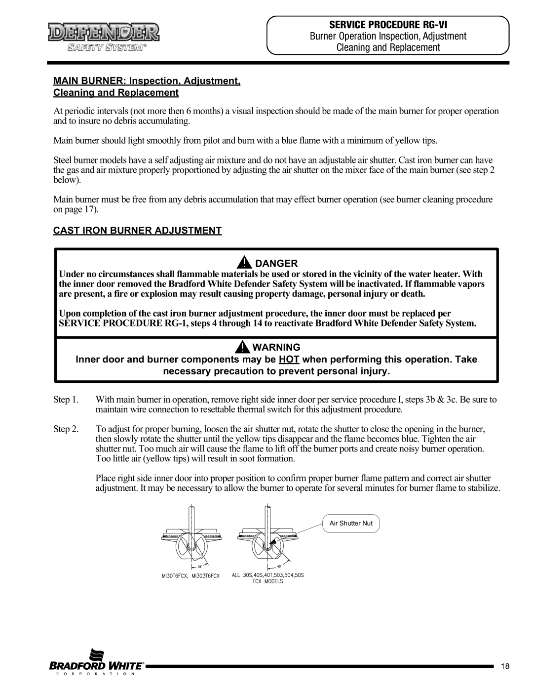
Step 2. To adjust for proper burning, loosen the air shutter nut, rotate the shutter to close the opening in the burner, then slowly rotate the shutter until the yellow tips disappear and the flame becomes blue. Tighten the air shutter nut. Too much air will cause the flame to lift off the burner ports and create noisy burner operation. Too little air (yellow tips) will result in soot formation.
Place right side inner door into proper position to confirm proper burner flame pattern and correct air shutter adjustment. It may be necessary to allow the burner to operate for several minutes for burner flame to stabilize.
Air Shutter Nut
18