General |
| MAINTENANCE | |
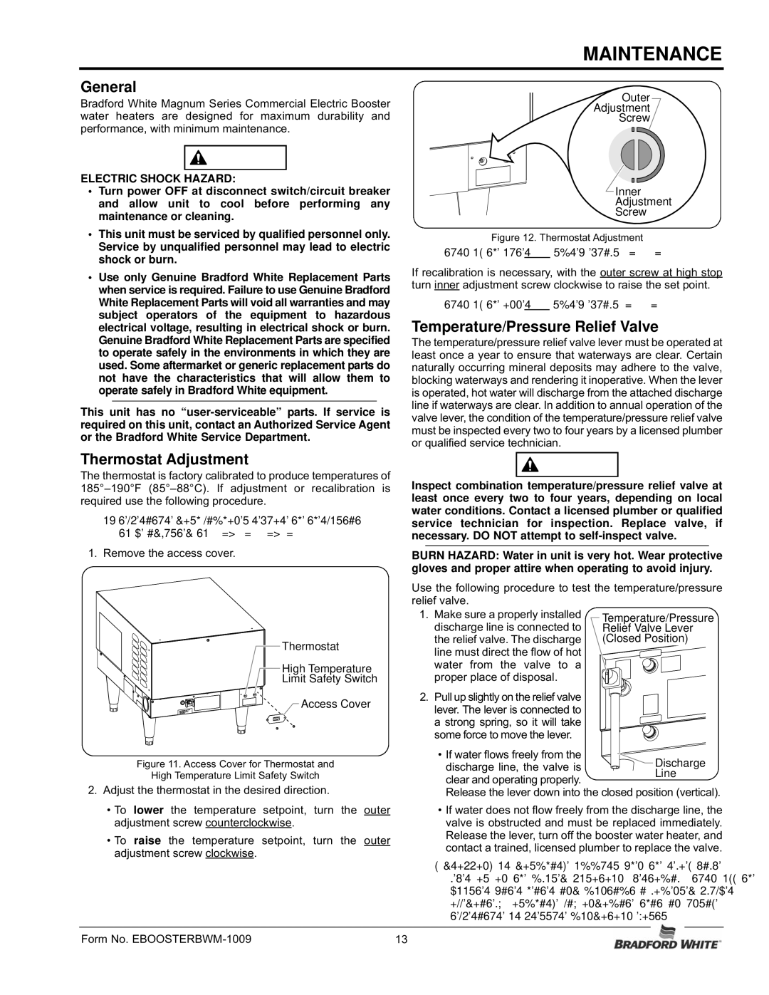
| Outer | ||
Bradford White Magnum Series Commercial Electric Booster |
| Adjustment | |
water heaters are designed for maximum durability and |
| Screw | |
performance, with minimum maintenance. |
|
| |
WARNING |
|
| |
ELECTRIC SHOCK HAZARD: |
|
| |
• Turn power OFF at disconnect switch/circuit breaker |
| Inner | |
and allow unit to cool before performing any |
| Adjustment | |
maintenance or cleaning. |
| Screw | |
• This unit must be serviced by qualified personnel only. | Figure 12. Thermostat Adjustment | ||
Service by unqualified personnel may lead to electric | NOTE: 1/6 turn of the outer screw equals 12°F (6.7°C). | ||
shock or burn. | |||
• Use only Genuine Bradford White Replacement Parts | If recalibration is necessary, with the outer screw at high stop | ||
when service is required. Failure to use Genuine Bradford | turn inner adjustment screw clockwise to raise the set point. | ||
White Replacement Parts will void all warranties and may | NOTE: 1/6 turn of the inner screw equals 8°F (4.4°C). | ||
subject operators of the equipment to hazardous | Temperature/Pressure Relief Valve | ||
electrical voltage, resulting in electrical shock or burn. | |||
Genuine Bradford White Replacement Parts are specified | The temperature/pressure relief valve lever must be operated at | ||
to operate safely in the environments in which they are | least once a year to ensure that waterways are clear. Certain | ||
used. Some aftermarket or generic replacement parts do | naturally occurring mineral deposits may adhere to the valve, | ||
not have the characteristics that will allow them to | blocking waterways and rendering it inoperative. When the lever | ||
operate safely in Bradford White equipment. | is operated, hot water will discharge from the attached discharge | ||
This unit has no | line if waterways are clear. In addition to annual operation of the | ||
valve lever, the condition of the temperature/pressure relief valve | |||
required on this unit, contact an Authorized Service Agent | must be inspected every two to four years by a licensed plumber | ||
or the Bradford White Service Department. | or qualified service technician. |
| |
Thermostat Adjustment | WARNING | ||
The thermostat is factory calibrated to produce temperatures of | |||
Inspect combination temperature/pressure relief valve at | |||
required use the following procedure. | least once every two to four years, depending on local | ||
NOTE: Low temperature dish machines require the thermostat | water conditions. Contact a licensed plumber or qualified | ||
service technician for inspection. Replace valve, if | |||
to be adjusted to | necessary. DO NOT attempt to | ||
1. Remove the access cover. | BURN HAZARD: Water in unit is very hot. Wear protective | ||
| gloves and proper attire when operating to avoid injury. | ||
| Use the following procedure to test the temperature/pressure | ||
| relief valve. |
| |
| 1. Make sure a properly installed | Temperature/Pressure | |
| discharge line is connected to | Relief Valve Lever | |
| the relief valve. The discharge | (Closed Position) | |
Thermostat | line must direct the flow of hot |
| |
High Temperature | water from the valve to a |
| |
Limit Safety Switch | proper place of disposal. |
| |
| 2. Pull up slightly on the relief valve |
| |
Access Cover | lever. The lever is connected to |
| |
| a strong spring, so it will take |
| |
| some force to move the lever. |
| |
Figure 11. Access Cover for Thermostat and | • If water flows freely from the | Discharge | |
discharge line, the valve is | |||
Line | |||
High Temperature Limit Safety Switch | clear and operating properly. |
| |
2. Adjust the thermostat in the desired direction. | Release the lever down into the closed position (vertical). | ||
• To lower the temperature setpoint, turn the outer | • If water does not flow freely from the discharge line, the | ||
adjustment screw counterclockwise. | valve is obstructed and must be replaced immediately. | ||
• To raise the temperature setpoint, turn the outer | Release the lever, turn off the booster water heater, and | ||
contact a trained, licensed plumber to replace the valve. | |||
adjustment screw clockwise. | NOTE: If dripping or discharge occurs when the relief valve | ||
| lever is in the closed position (vertical), turn off the | ||
| booster water heater and contact a licensed plumber | ||
| immediately. Discharge may indicate that an unsafe | ||
Form No. | temperature or pressure condition exists. | ||
13 |
| ||